Jun 142015
 

P-T_w_Camera_03

So… this is one of those posts I have been needing to do for a long time, but when I looked at the project I kept asking where the heck does one even start? The majority of this was built around May of 2015 and I will be back dating this post to reflect that. The wording is written as if I wrote it back then to keep the tenses at least a little bit proper, but as usual, grammar police be warned… Dangerous reading ahead. Also, this was a project that had many areas being developed at the same time, so while I will try to write things as linear as possible, it will not be, it can’t be, and it wasn’t. Now on with the show…

Slider_Old

A couple of years ago I built a camera slider for my brother based on a design by J.G. Pastorjak. While I was doing the research about how to build it, I decided to build one for myself as well. This was a simple slider which worked very well, provided some wonderfully smooth video, and I have used it a lot. The time-lapse community have made several advances using sliders. Shots in which the camera is actually moving in during the time-lapsed event. It’s very complex and beautiful movement. While I suppose this could be done without computer / machine control, someone is going to have a really bad day trying to do it. I have also been following the work of some of the higher end commercial slider systems which not only moved the camera within the time-lapse, but it also included automated pan and tilt. These were the sorts of goals I wanted design and work for. While I suppose I could have saved some money and time and just bought the dern’d thing, that’s not how I tick. More, I didn’t want to be limited by the features that someone else dictated to me based upon some sort of pricing structure. I want to understand it, explore it, and most importantly make it my own. I did a ton of researching and reading trying to find answers and solutions. While I found a few people who have ventured down this alleyway, I couldn’t find anything like what I was personally imagining, or wanting.

A few items which I wanted (the basics)…

  • Pan, tilt, and slider (duh)
  • Must be self contained.
  • Must be able to be used for both video and stills (time-lapse).
  • Should be easily convertible for new features.
  • Should be smallish in size.
  • In stills mode, the controller will also trigger the camera shutter.
  • I wanted to reuse as much as I could of the slider I had originally built.

Then there were the constant burning questions which gummed up the process…

  • What type of motors should I use? Stepper motors, standard motors with some sort of encoders, servos?
  • Does the slider engage with a ball screw, rack & pinion gears, or belt feed?
  • What materials would I use for the slider, the deck, the moving bits?
  • How would the pan and tilt actually work? Belt, worm gear, direct drive?
  • If it was self contained, how would I control it (without needing a laptop)?
  • How would I power it?
  • How would I connect it to my camera (shutter release interface)?

I usually have 4 – 5 projects brewing at any given time. Probably more than that if I am being honest. Most of the time I will hit some cliff of impossibility or creative wall and stop that project for a while. I will then work on another while I mull over the issue. I am not an engineer by trade, but my engineer friends tell me I am one, just minus the degree. It’s just how my mind works. These problems are like brain puzzles. There has to be a solution, so sometimes I will plow into a project without fully knowing if it will pan out (pun not intended). This project was no different. There were some pretty hard issues to resolve here. It covered so many areas of discipline… Mechanical, structural, electronics, programing, and general artistic aesthetic.

Screen Shot 2015-06-22 at 8.08.35 AM

My thinking was that I needed to work on the slider trolly portion (called the ‘slider’ from here on) first because if there’s no slider, there’s nowhere to place the motors, or camera. Pretty straight forward, right? I am sure that this is going to start sounding very circular, but stick with me. One issue I had with the original slider is that it could get a little wobbly if I got some weight on it. So I decided to re-deck the slider for extra rigidity. I started to think about what size the deck would be and realized that the deck would be based upon the distance between the rails + the width of the wheels + a little extra for fine tuning. It then occurred to me that if I am cutting the deck out, I also need to think through where the pan and tilt would live on that deck. If the pan and tilt are on the slider, then the motors will also be on the slider. If the motors are on there, how do I get wires to it. Wait… if it has wires and it is spinning, how do I keep them from getting caught up on itself. In the end, I realized that I was going to be designing the whole pan, tilt, deck, and slider assembly at the same time.

MYX_Logo_Milling

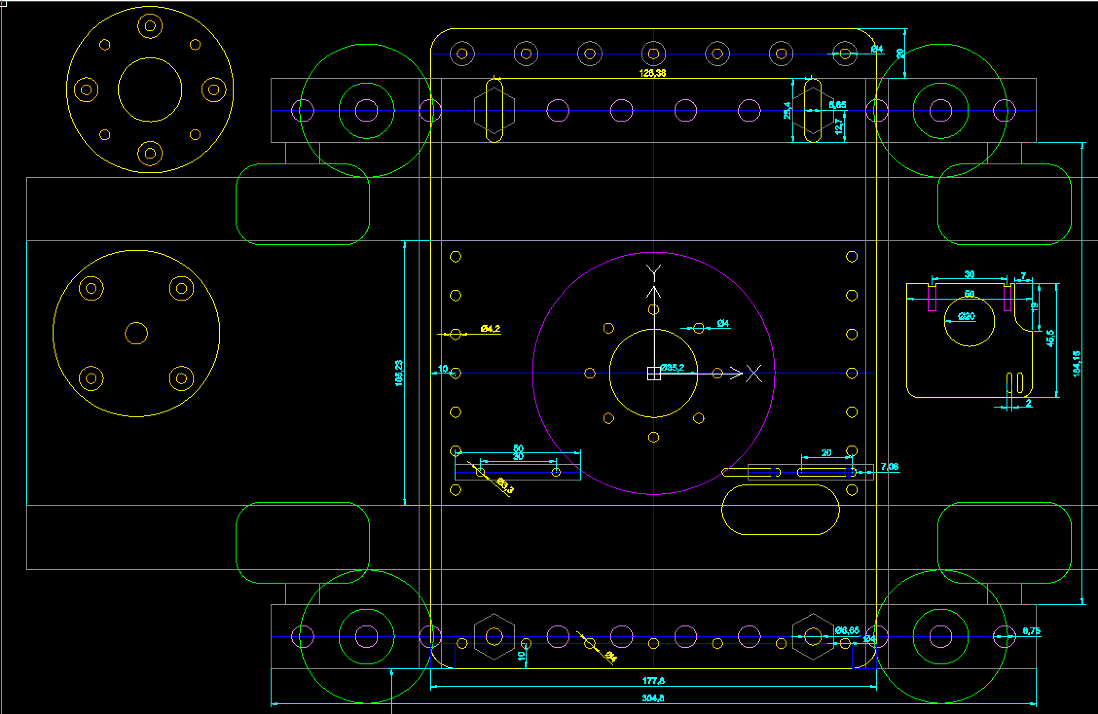
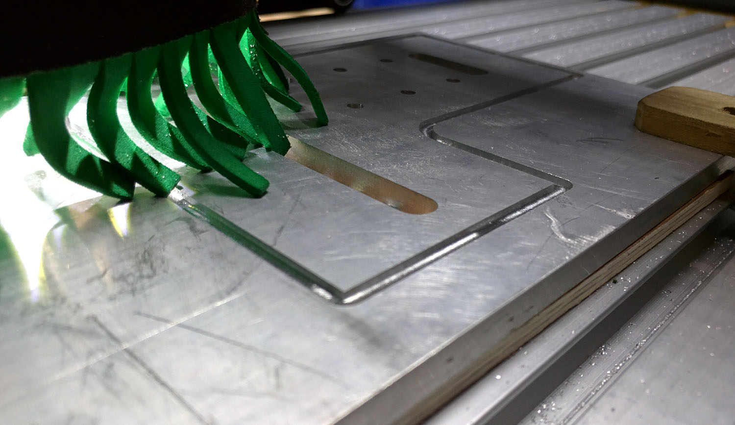
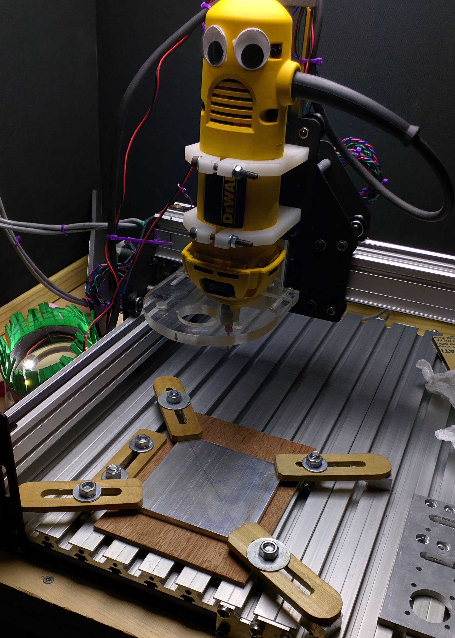
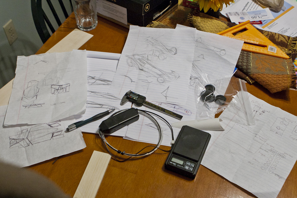
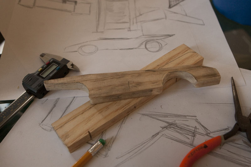
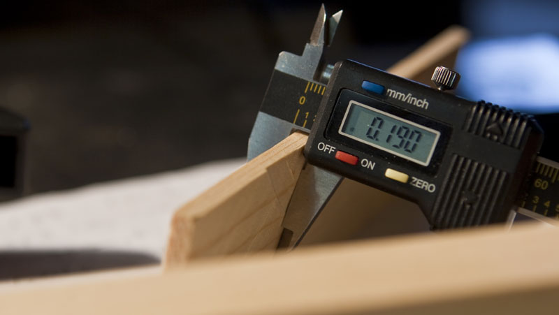
While the Shapeoko II is an amazing machine and is completely capable of making beautiful things, it’s not a exactly speed burner. When cutting aluminum, parts could take up to 4 hours to cut out. With that time commitment, I didn’t want to remake parts if I could help it. With this in mind, there was a lot of benefit of thinking through the whole mechanism. I was using Draftsight for the design. Sometimes the hardest part is starting. Where do you start? Eventually I just started placing design ideas with rough spacing. Once I started seeing something I liked, I then started taking measurements and dialing it in. This of course meant that lots of things needed to shift, but the idea was there.


EndCaps

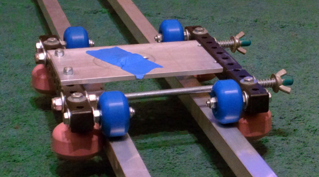
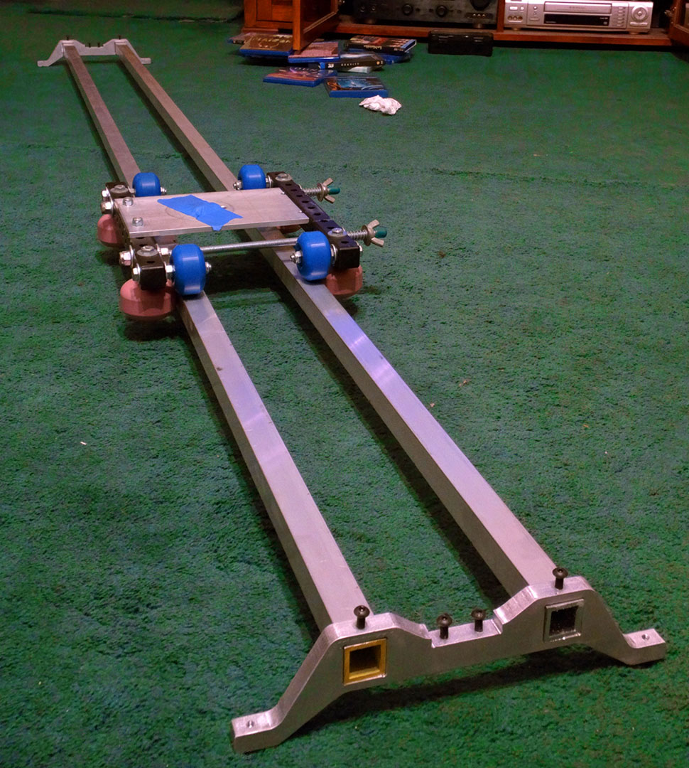
I started work on the base of the slider system. This means the end caps which would support the rails on which the slider would slide… upon. My previous slider rails were 1 inch square aluminum tubes held together with 2 – 6 inch pieces of “all thread”. This put a 3 inch space between the rails. While this worked, as I mentioned earlier, it had the tendency to be a bit wobbly once you got a camera and head on it. To make things worse, the original rails were the stuff you find at Home Depot which had very thin walls and HD don’t tell you what grade of aluminum it is (several threads on the internetwebz says box stores are selling generic low grade 5052). I called and talked to a woman who said she would find out and get back to me (I am still waiting). I bought a new set of rails from Metal Supermarkets which are quite thick, and if the web is correct, a superior grade of aluminum (6061). I bought the new rails for less than the cost of the thin stuff from the HD (makes one think).

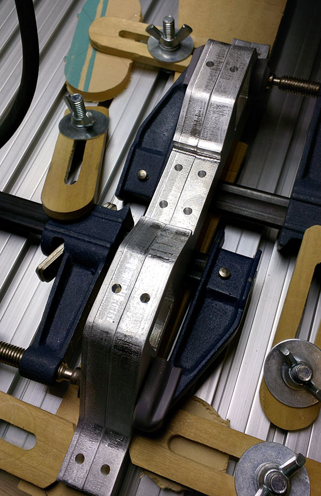
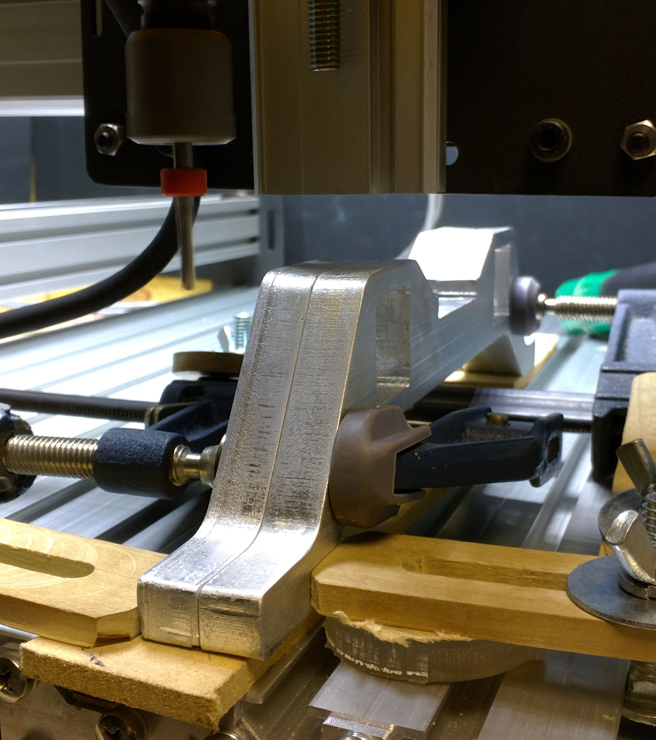
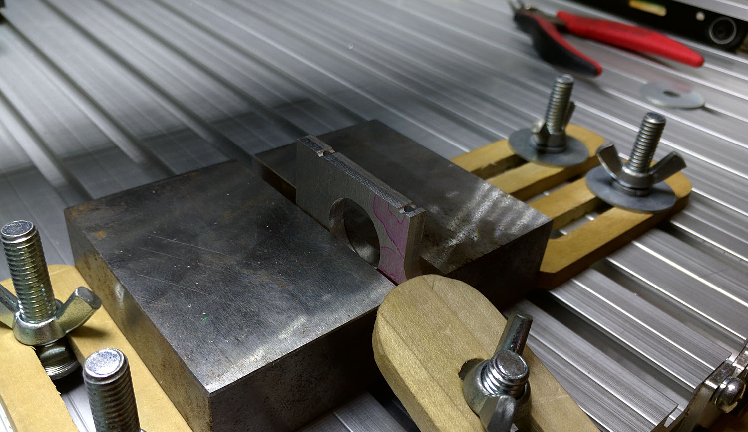
While it is not a huge increase, I spread the gap between the rails from 3 inches to 4 inches, hoping that the strength and extra width would make things more rigid. The rails are held together with custom aluminum brackets or end caps (no, I haven’t come up with an official name for them). These brackets were milled out of 6061 aluminum. Actually I’ll just place it here… everything on this project was 6061. It’s super strong, light weight, and can be machined well. The caps are a half inch thick which is probably a little bit overkill, but I don’t have to worry about them bending anytime soon.

PullyPlates_Side

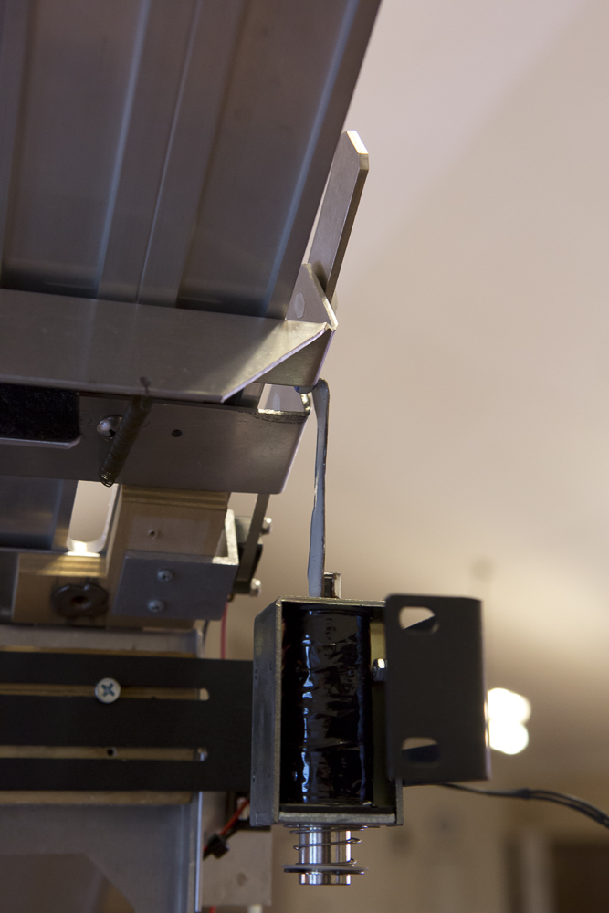
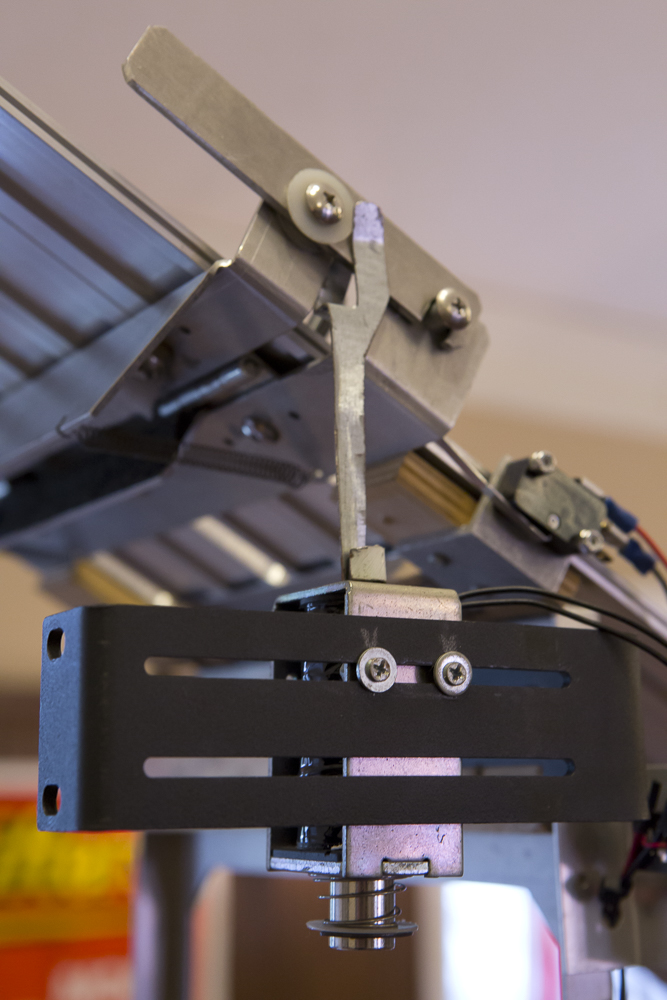
The caps have threaded holes in the leg sections in which leveling screws could be placed to allow the slider to be stabilized on just about any surface. They also have a set of holes for M5 screws to tighten down on to the rails, locking them in place. This is important so I can break the system down quickly and easily. There’s a notch cut out dead center to receive various types of mounts which can be screwed into (motor, pulley, etc.). I didn’t build any of these additions to be permanent (although they could be) as I wanted a test bed for further ideas after the slider system was complete. The pulley end plates have a recessed cut pocket for a bearing and a small hole in the center for a M5 screw to pass, through a geared pulley in between, through a second bearing, through the top plate which is then secured with a washer and locknut. There are 3 holes around the outside for m5 screws and a bushing. Once the bushings are in place the whole thing sandwiches together and locks tight.  The other end cap holds a fixture which holds the slider stepper motor. Again, this is attached via 2 – M5 screws.

PulleyPlate_Front


Arduino_Stepper

I am not going to go much into the angst and back and forth I went through trying to make some of my final decisions on various various parts unless it is absolutely necessary. Otherwise this will become a silly long blog post (which is already a bit too long), and you dear reader would probably need some serious therapy as a result. I settled on using stepper motors. Steppers offered me the assurance of repeatability and strength. For some effects work I am imagining, I will need to repeat the exact same move, over and over, many times. I need the camera to match up both in time and spatially, so exact repeatability is critical. The steppers I am using are Nema 17 Bipolar 64oz./in. and provide 200 steps per revolution. This  accuracy can be expanded by microstepping which splits each main step into smaller sub steps. The number of microsteps really comes down to the driver one chooses to use. Initially, getting up and running, I am using some of the super cheap knock off A4988 type drivers (There’s a lot of money falling into this project, so inexpensive while prototyping, yeah?). These are suppose to provide up to 16X or 3200 microsteps per revolution. The only problem with using microstepping is that I loose some holding torque when using higher levels of microstepping. This is not a problem if the slider is on a level surface, but it could potentially slip if I am trying to have the camera climb. So… build it, see what it can do, and update it as necessary.

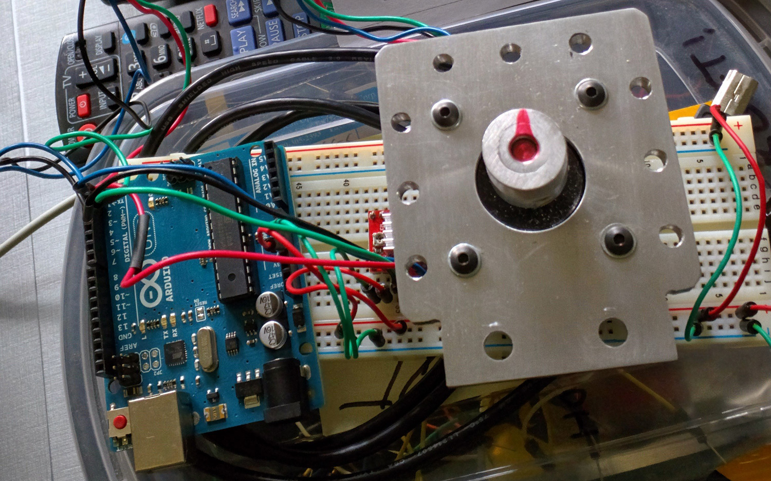
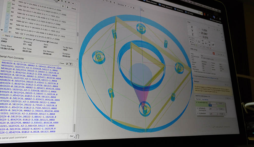
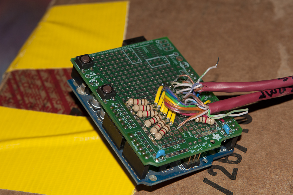
At this point it was time to get at least a basic amount of the automation work started with the current slider and the new rails. Clearly this would be a microcontroller driven thing. My go to microcontroller is of course the Arduino. I knew it would be more than capable of the movement as that’s what’s driving my Shapeoko, and if you think about it, this is really just a CNC machine with a camera attached. Getting the stepper going was not too hard, while getting it moving smoothly, was. Let me rephrase, the linear movement was perfectly smooth. It was just getting an object to ramp into up into motion without a heavy jerk was somewhat problematic. Software can be fixed. Mechanical issues, would have needed to be tweaked and rebuilt. Being that this was a software thing, I moved on. Eventually I found an Arduino library that let me set a specific distance and it would ease in and out of the movement. The video below shows that progress. I am sorry for the crap quality, but at that moment, it was very exciting and I wanted to capture it’s first real steps. The belt was attached by being sandwiched between a couple washers and screwed tight. A more permanent solution was designed for the new deck, but hadn’t been cut out yet.

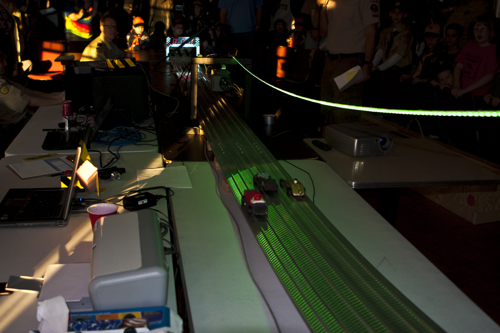
Below is a video of the first bits I shot with a camera, the new end caps, new rails, pulley and motor mount, but with previous slider. I was grilling out on back porch, so I figured I would take out slider and give it a try in between burger flips. While it’s not an Oscar winner (nor all that entertaining), you can see that it is very smooth. Speed was not the goal here. I was curious (concerned) to that I would see stutter(ish) motion artifacts at really slow speeds caused by the stepper’s movement which by it’s nature is based upon pulses. Would this translate into the video? I was really happy to find that it was buttery smooth. I will point out that at about 13 seconds into the video, you can see the image shake. This is a result of the sudden jerk into motion when the slider started to move. This was before putting on the new deck, so effectively the camera was suspended over the center of the slider (only connected from one of the sides). I had to detach the deck from the other wheel fixture due to the wider width of the gap between the rails. The new deck helps this a lot, but again, this is why I need to get some easing worked into the motion portion of the programming. Smooth movement from a stop, up to speed, then smooth slow down, and stop.

ServoCity_Stuff

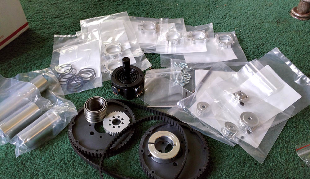
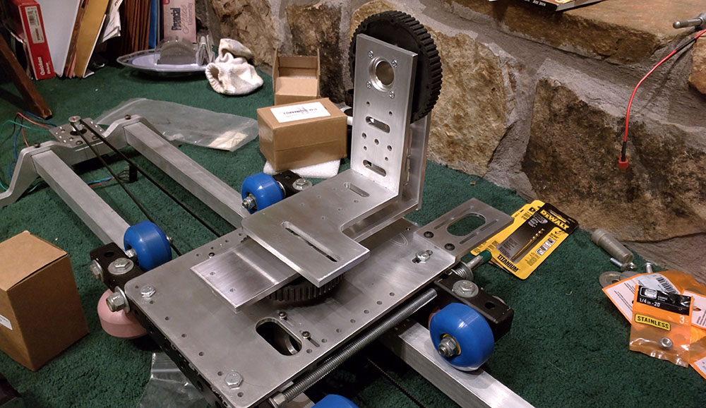
The motors somehow need to connect to the slider if things are going to move, right? I decided that it would be belted gears. The idea being that I could tension the gears and motors after building everything. I can also re-gear things if the movement is too fast or slow. While I am all for building my own things, there are some items in which I felt there was no need to reinvent the wheel. Gears, pulleys, and belts need to be exact for things to run smoothly. Most of these types of items I purchased from Servo City as they have some really beautiful stuff. Everything else was built from scratch.

TopPlate_Attached

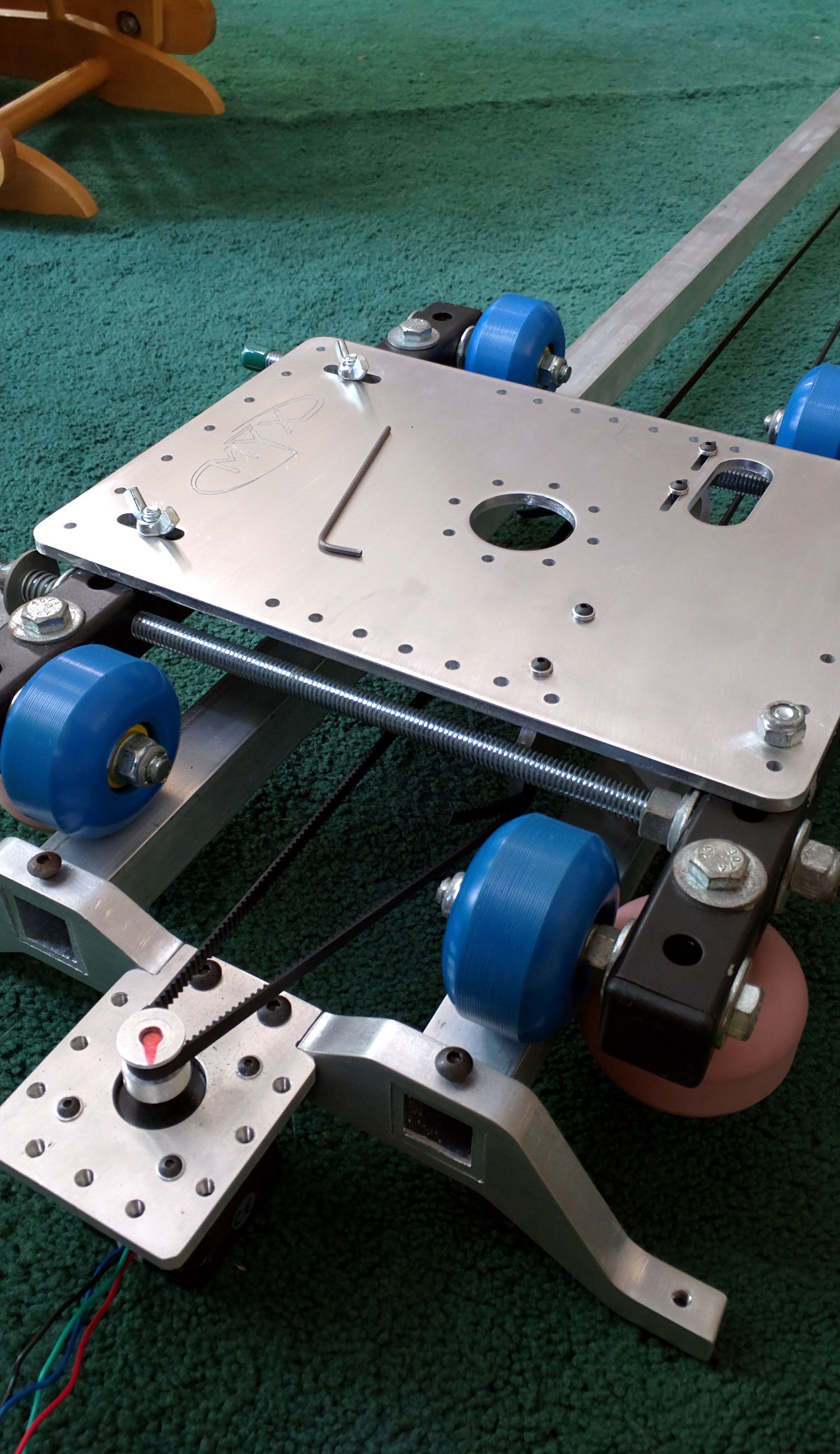
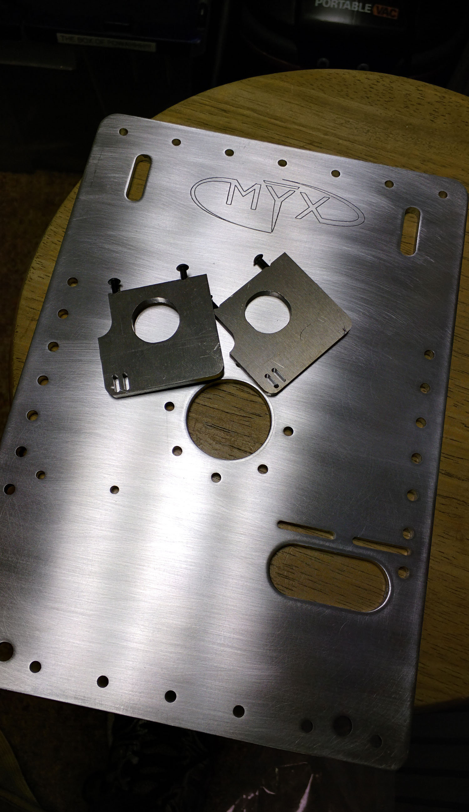
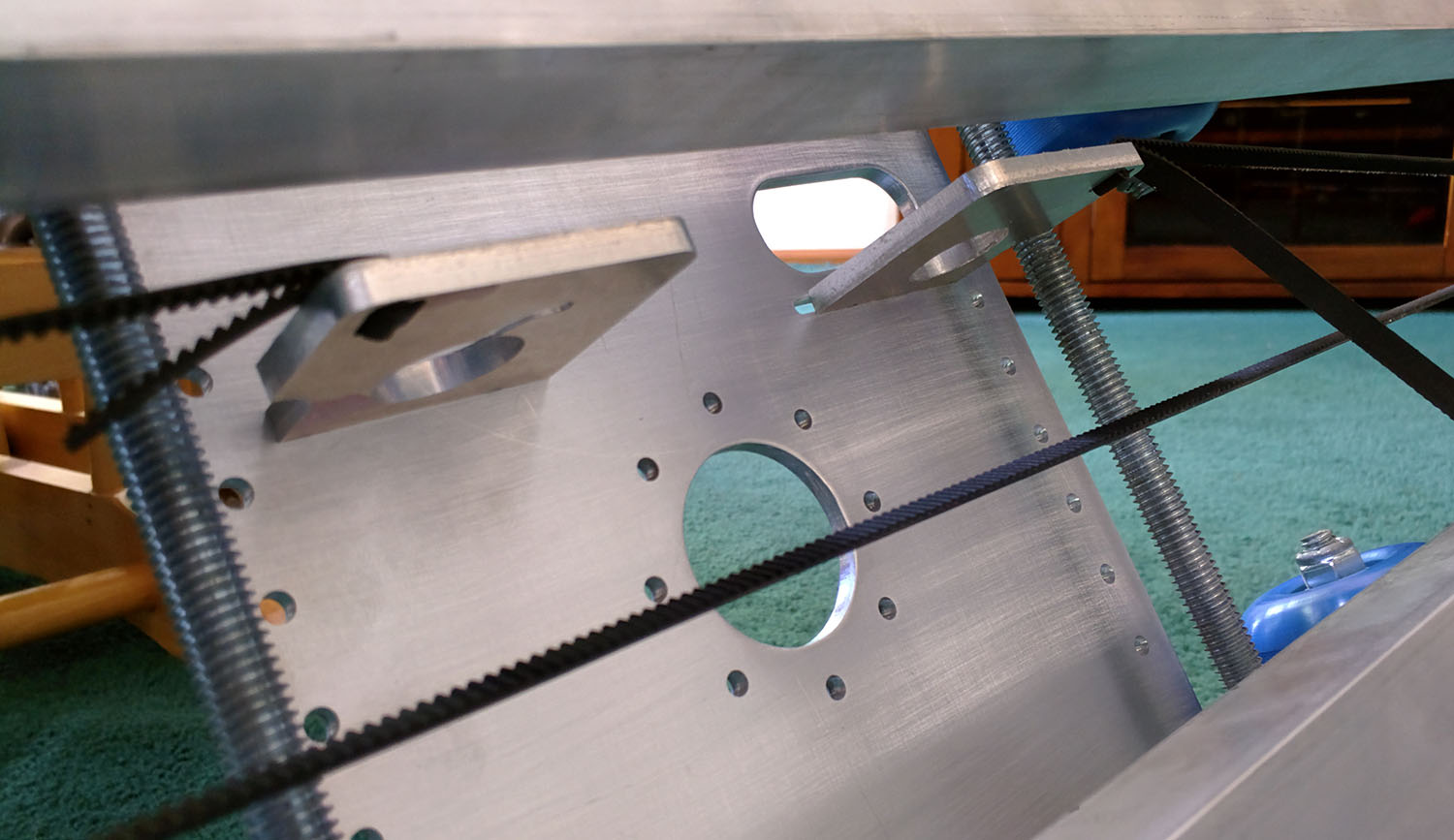
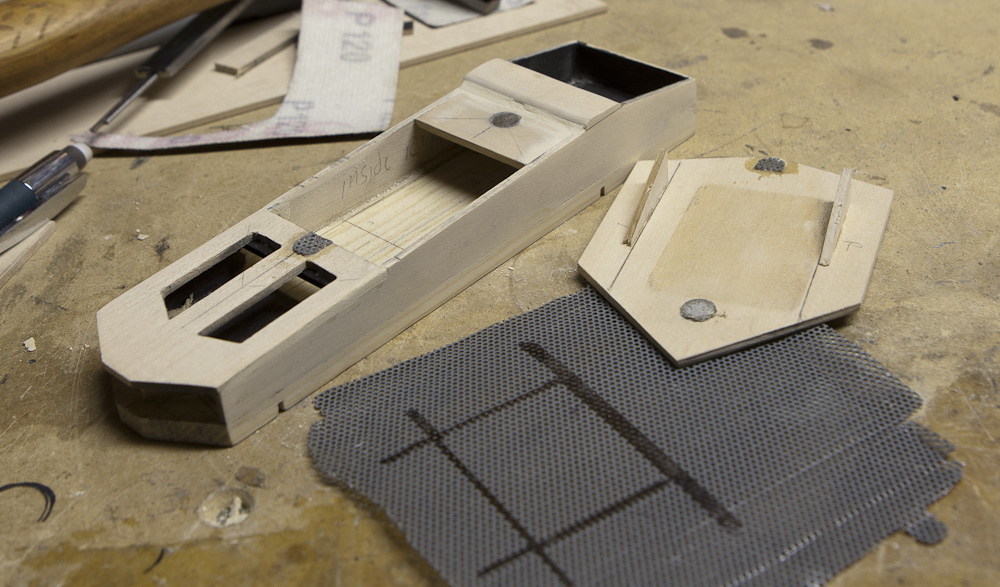
The center point which ties everything together, is the deck.  The deck was designed with attach points all around it in the form of tapped holes, so that there would be gobs of options. While I am not sure if this was a good idea or not yet (only time will tell), but I made all the hole spacing on one deck axis in inches, and millimeters in the other. BeltBlocks_02
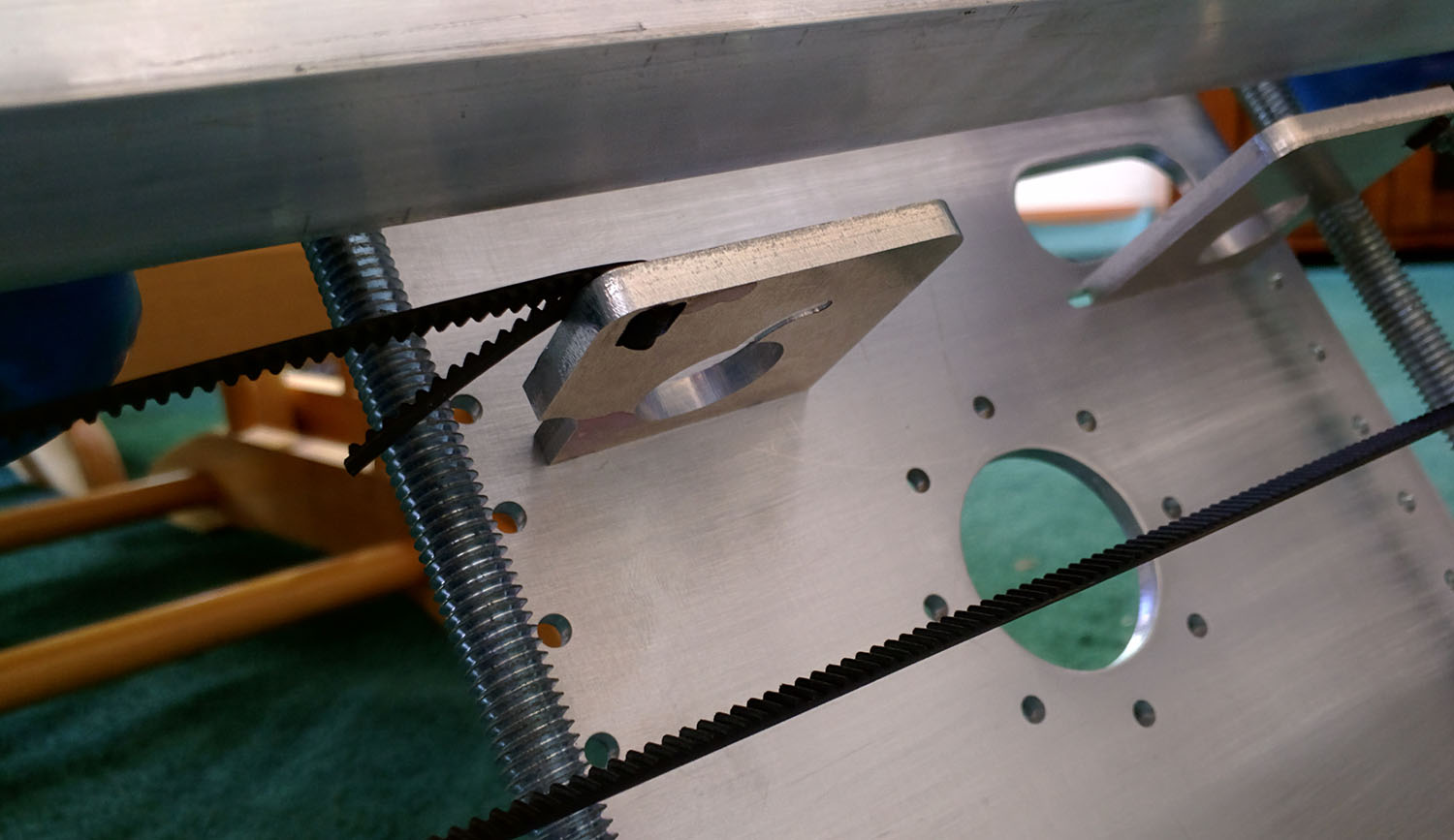
My thinking is that perhaps someone would produce something I might want to attach, so why not try to make it somewhat universal. I have been trying to keep everything I build as metric, just because it’s wonderful to work with, but made an exception here. The deck also has attachment points for the wheel rigs. There are points for the belt connection plates and a finger hole for tensioning them. The belt connection plates are what physically attach the slider to the stepper. The belt is easily fed through these slots in the plate, but once the belt is tensioned, there’s no worry of it slipping back out. These are held in place with M3 screws.

Pan-Tilt-w-Steppers-Belts

P-T_w_Camera_01

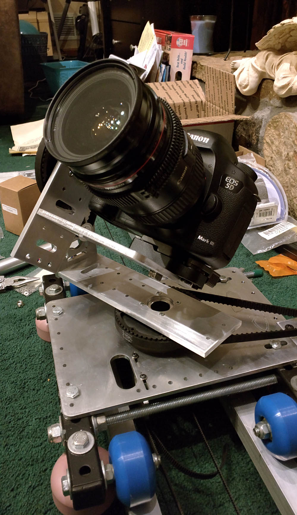
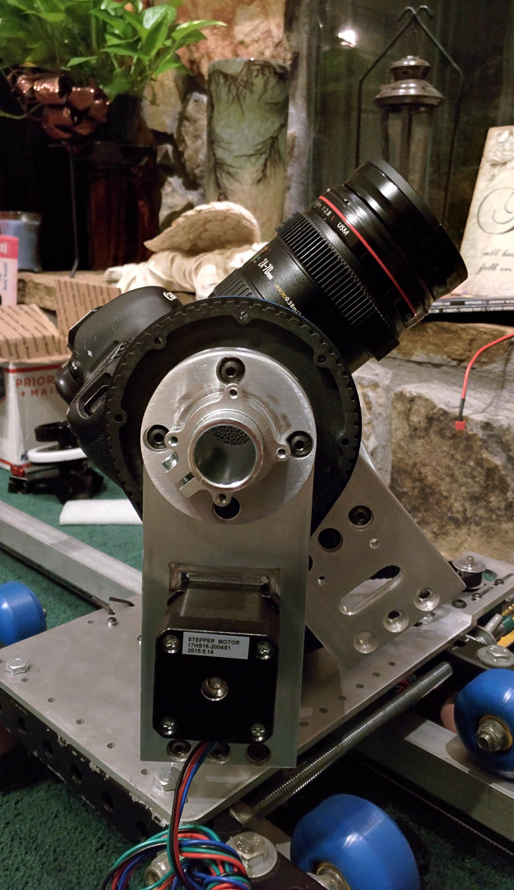
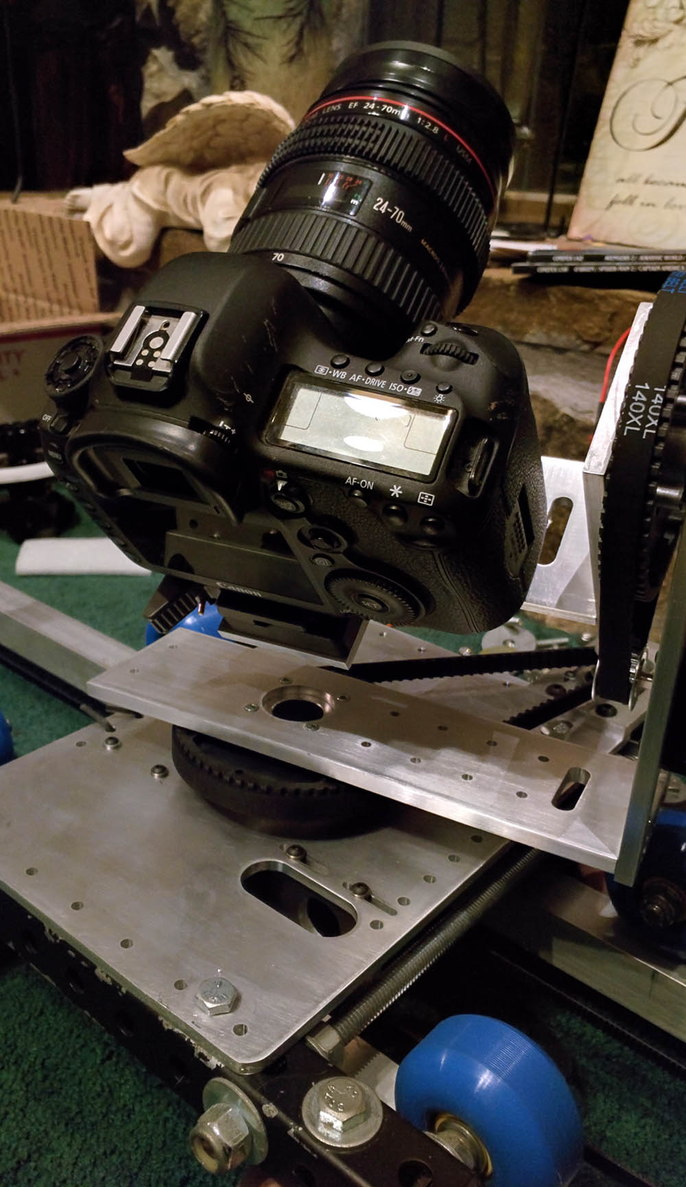
I am currently shooting with the Canon 5D mkIII and Panasonic GH4, so I have built the slider around the 5D as it was the bigger of the two. This thing is going to be carrying a lot of wiring which has to reach from the outside the slider all the way up through the pan and tilt arms and up to the camera. I concocted a number of ways to do this, but they were all limited in some way.

Then I had an ‘aha’ moment. Adafruit announced a slipring wiring harness. While this product didn’t make it very far in my design, it was the idea of the wires being integrated into rotational axis that got me. The reason being is that I could do a couple of rotations without causing harm. I started digging into the ServoCity site and on paper put together a stack of items which would provide this cored rotation.

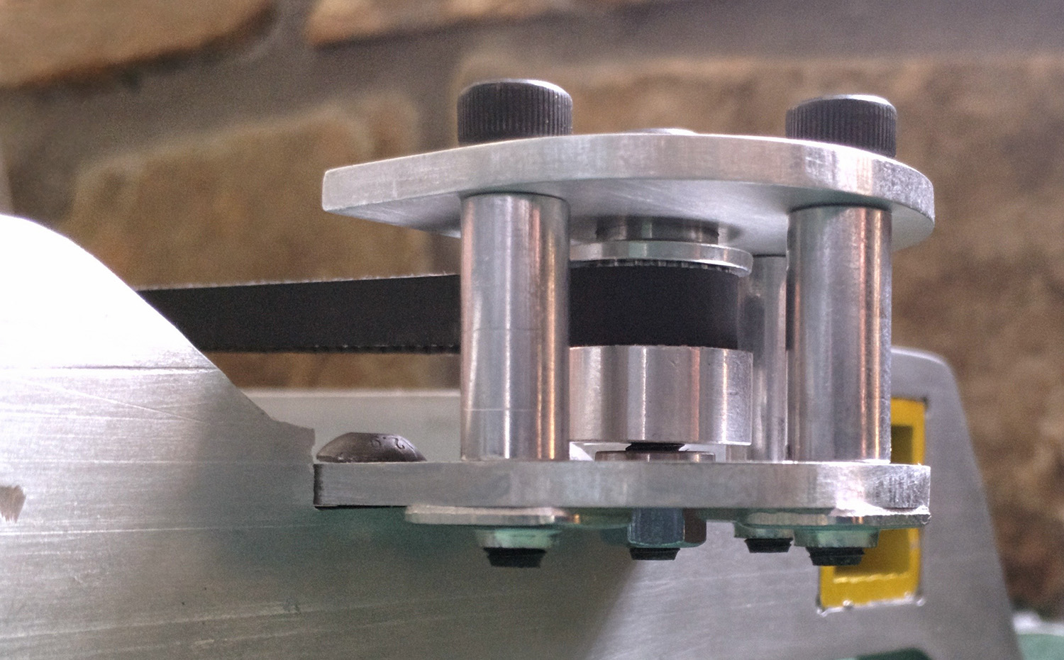
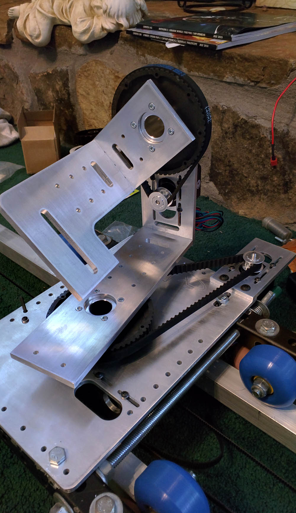
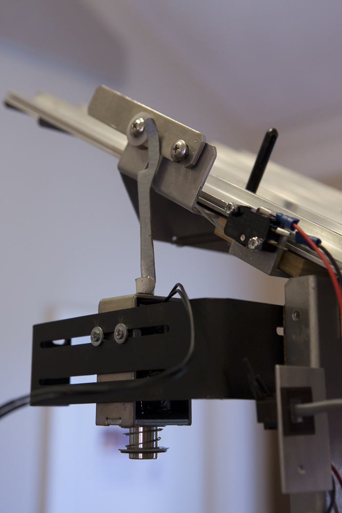
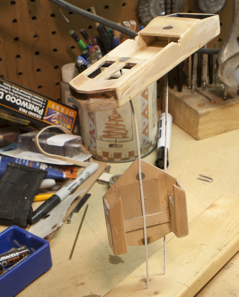
The item the brought it all together was a set of crazy thin bearings with a huge center bore. These were used on both the pan and the tilt axis. The tubes were flanged on one end which provided a base to which everything could stack and lock to. I will try to explain the stack, but it’s a little convoluted in text. TopPlate_w_Pully_AssemblyTopPlate_w_Pully_01
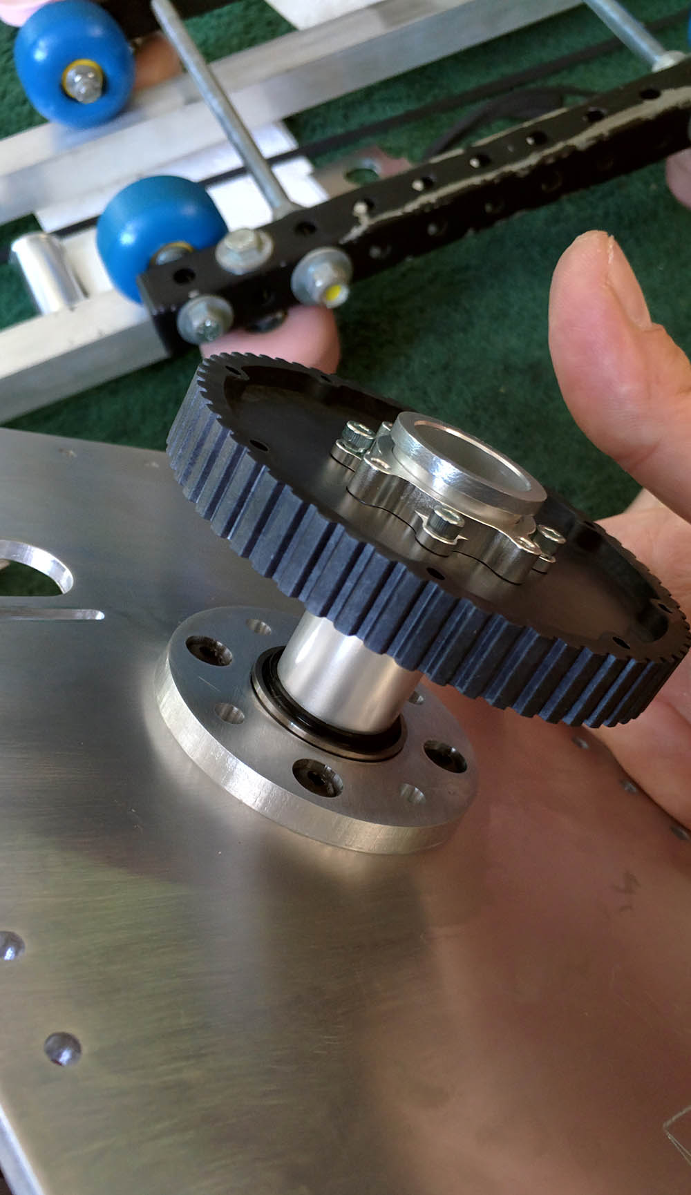
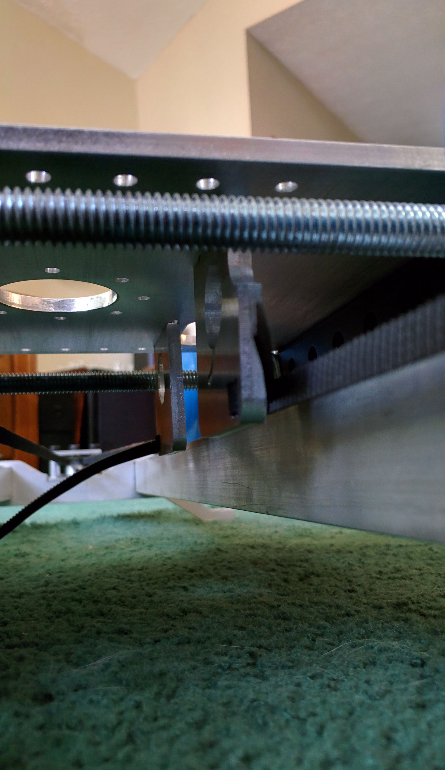
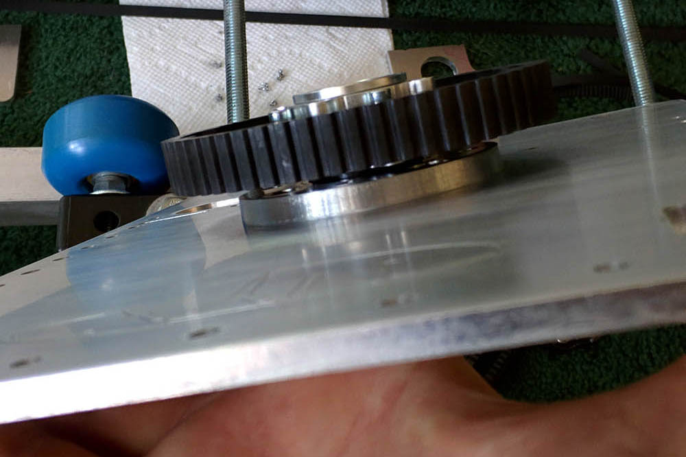
For the rotational base, the tube was fed through a hub which would lock onto the tube. The tube is passed through a large pulley and the hub is screwed to that. The tube is then passed through a very thin plastic washer, and then one of the ultra thin bearings. There are 2 milled plates which sit on top and underneath the slider deck. These plates have pockets cut to exactly fit these bearings. TopPlate_Under_w_BearingClamp
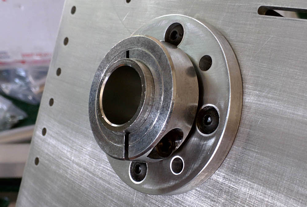
These plates are bolted to the deck to provide a secure rotational center. The tube coming out the other side of the slider deck and bearing plate is then passed through the second bearing, through a plastic washer, then the bottom hub lock. The only difference with the tilt axis is that the tube passes through another inside riser piece which ultimately connects to the camera plate. I am sure that this was a bit hard to follow, so hopefully the photos spell it out a bit more clearly.

Tilt_Camera_Plate

I wanted the pan to around the nodal center of the lens. If the lens sits too far forward, a pan can feel more like a swing. Being that different lenses would have different points, I have built in a a slot to allow for forward, and backward movement.  I also built in the ability to put the camera plate at several height levels so I can change how the camera tumbles, or allow space for an extended battery pack. Basically I built in a ton of options I which I might or might not need, but wanted the option. I also added many spots for other things to be attached, and wires to be strapped to. Zip ties will keep things wired flat to the plates and I have cut slots which the wires can cut back and forth to stay out of the way of the rotating arms. I am making this sound somewhat easy, and it wasn’t. There were several attempts on a couple of these parts which ended in sadness due to unforeseen spacing issues, bearing pocket being on the wrong side of the piece (I was trying to do some 2 sided milling which is quite difficult to do and keep things perfectly aligned).

4DScreen
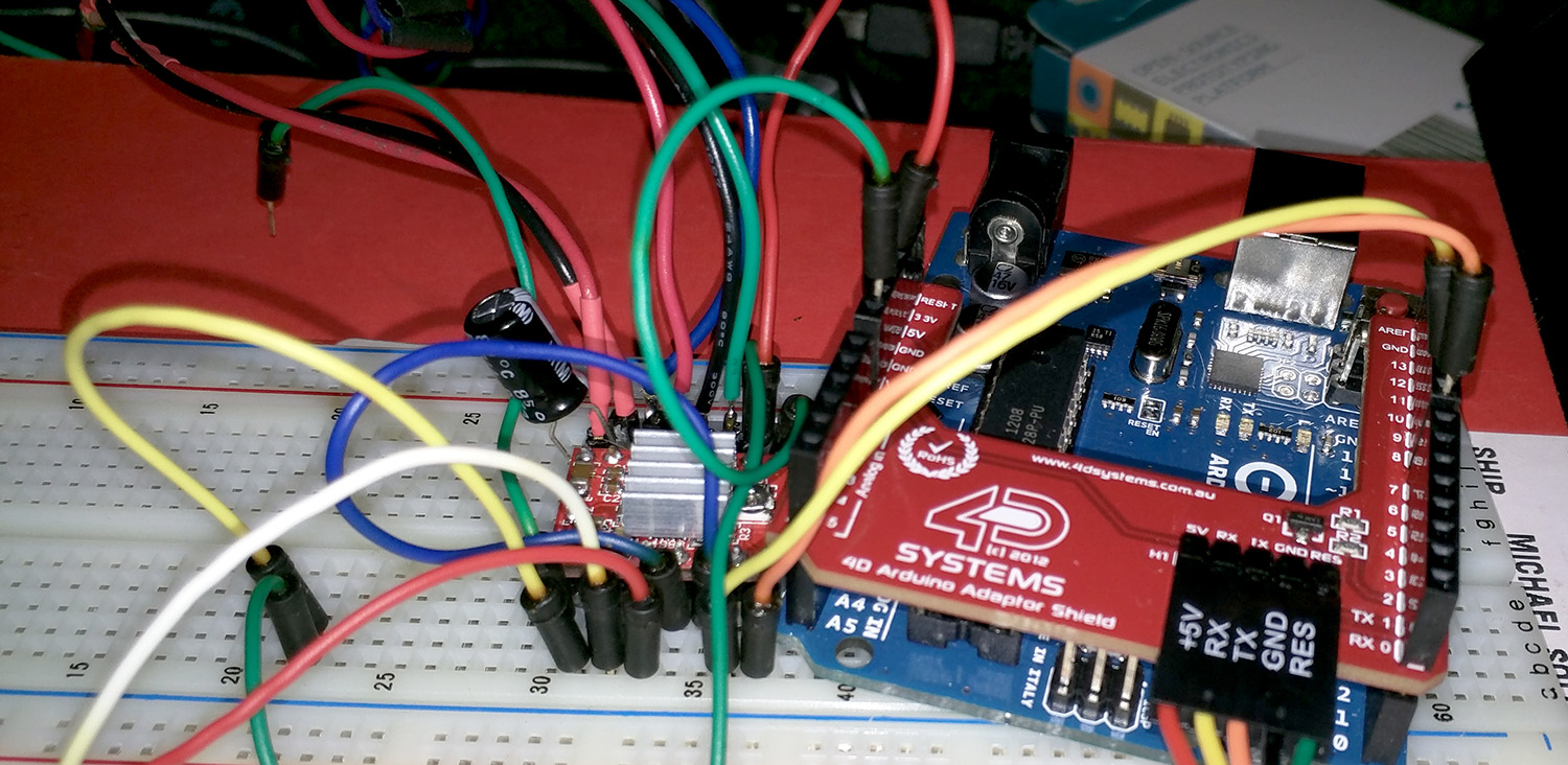
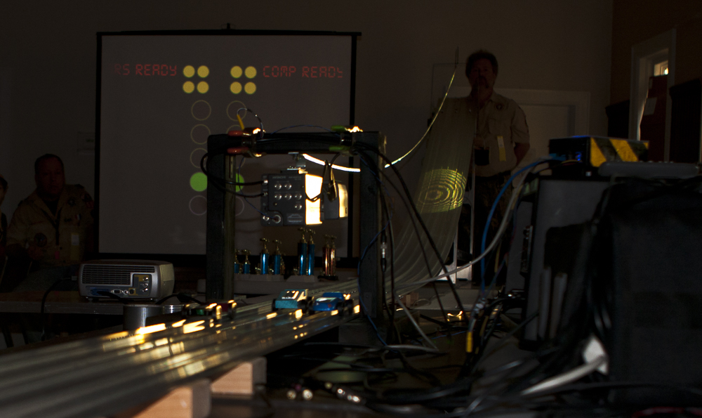
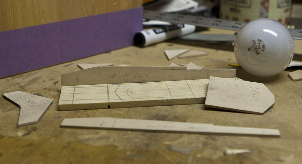
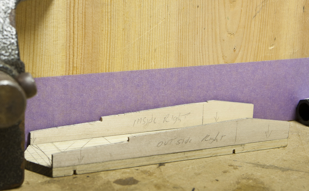
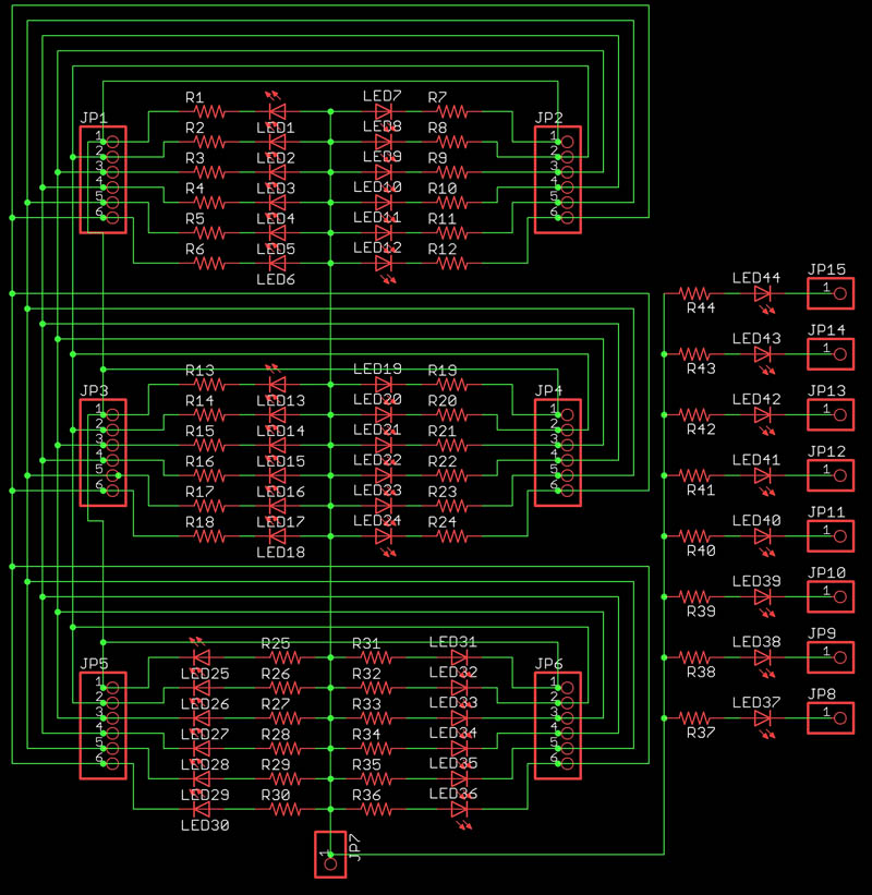
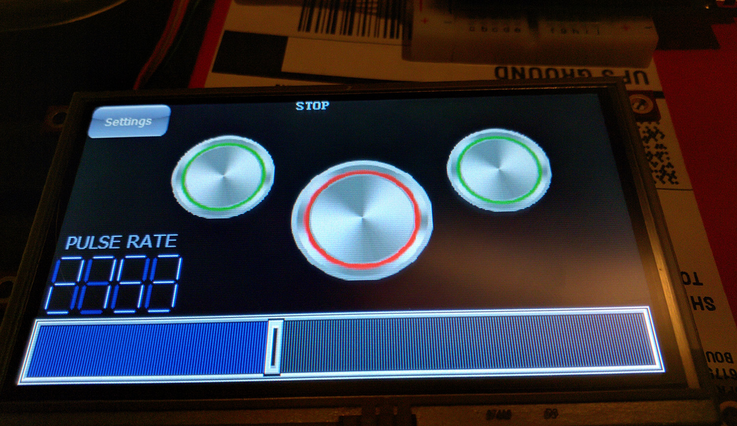
Meanwhile… Back at the batcave… The previous video was being controlled from my laptop. I needed a way to control this thing remotely. I wanted both immediate physical control (joystick) and programmable control for repeat performance. I needed something which could provide visual feedback as well as let me know the status of the system. I decided to use a 4D Systems touch screen instead of a bunch of dedicated physical buttons and switches. Sure… why not throw in a whole throng of unnecessary hardship in my path when I could have just made life far easier with physical real world things… but no, I had to go way too far off the deep end and go all touch screen. Controller_Tape

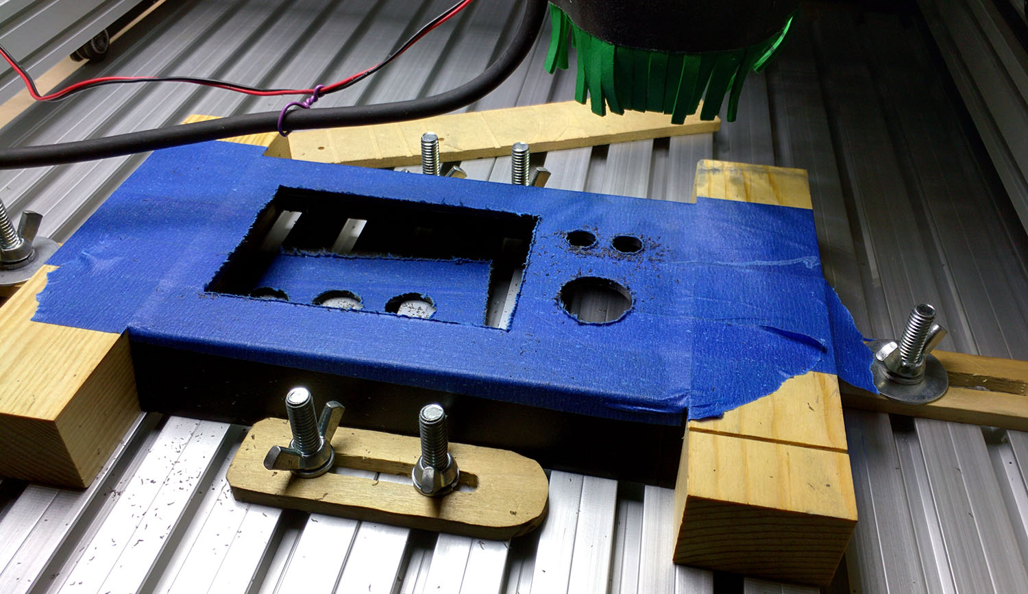
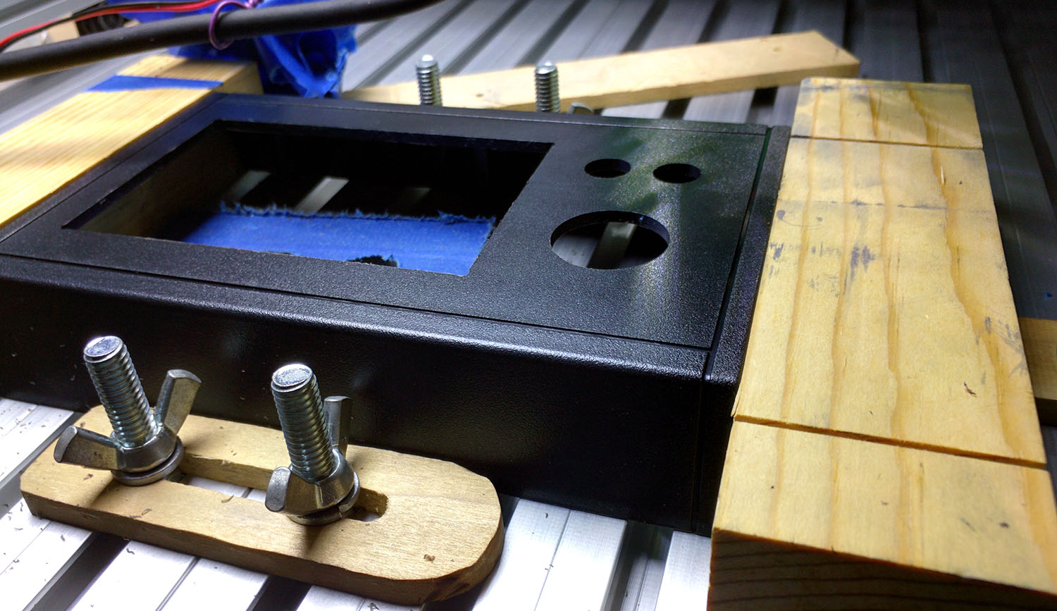
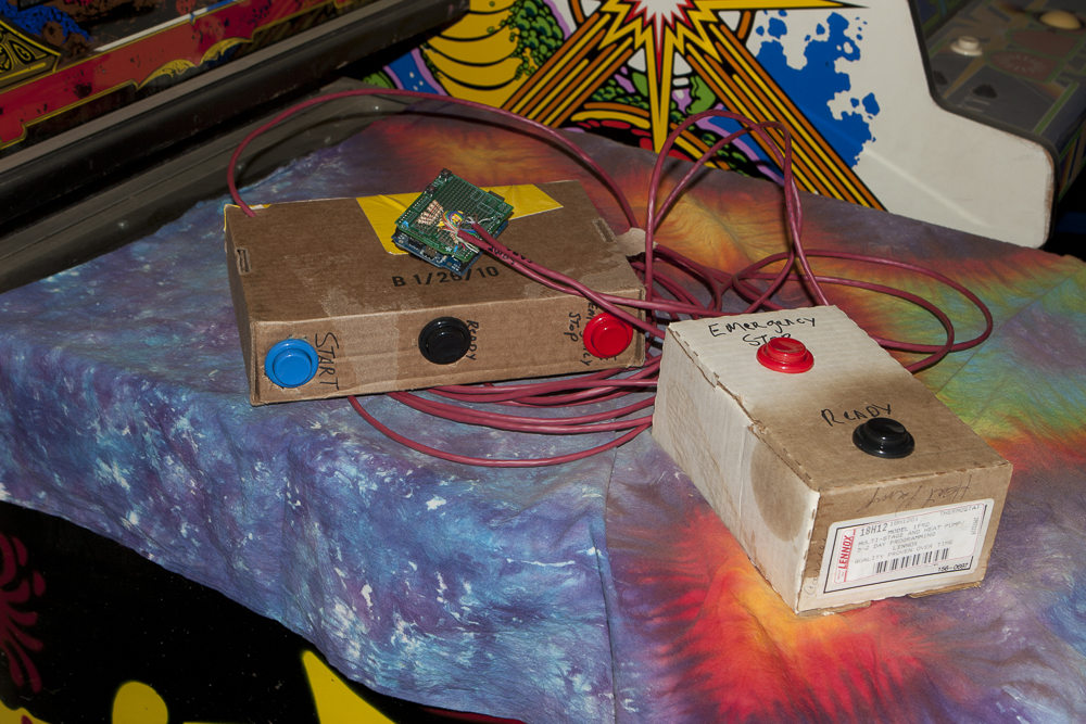
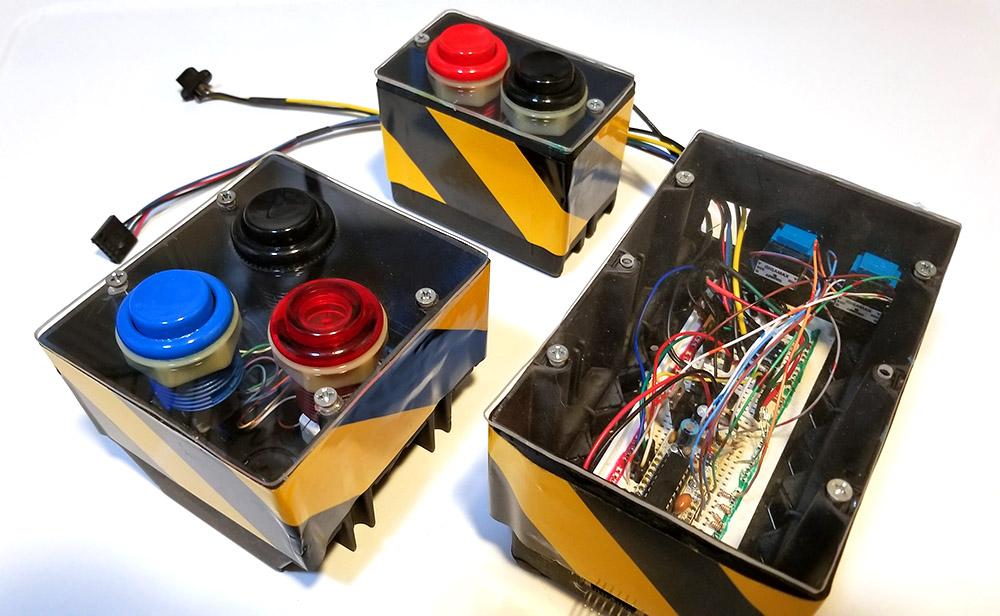
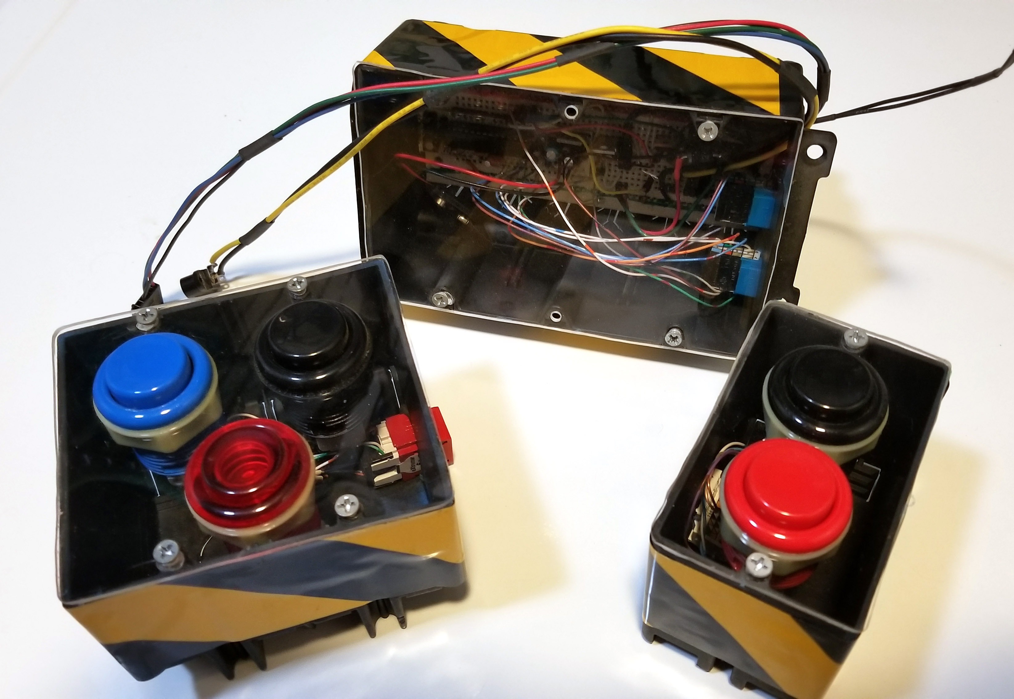
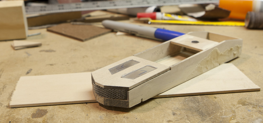
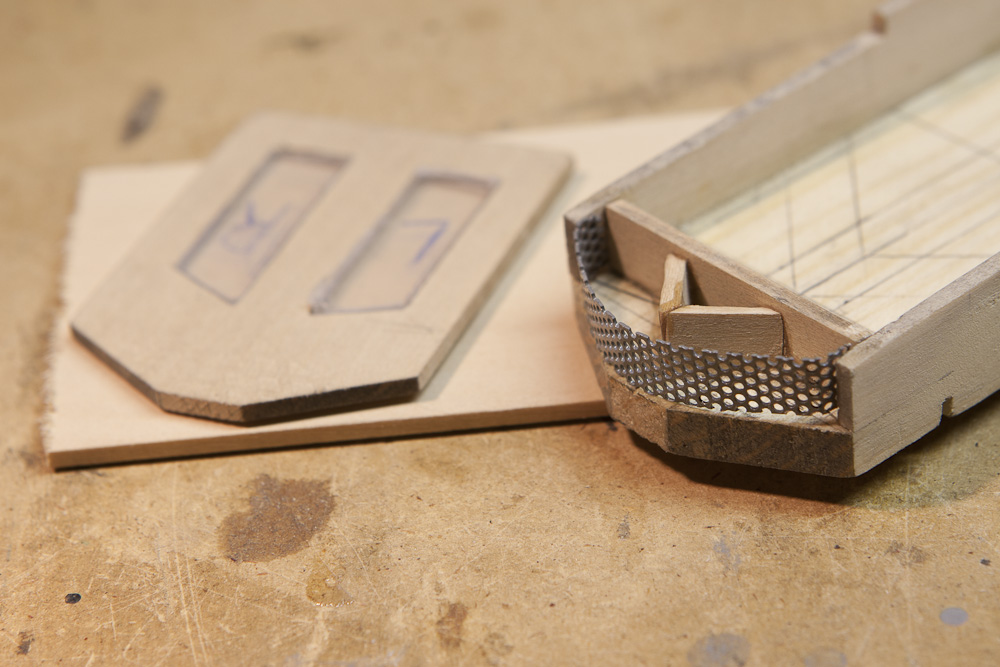
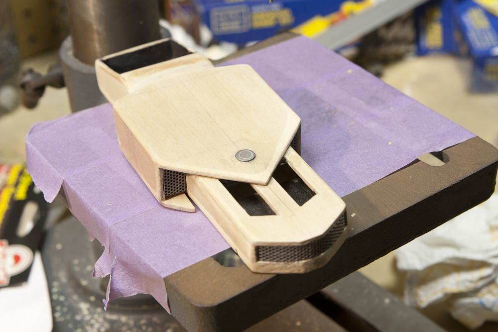
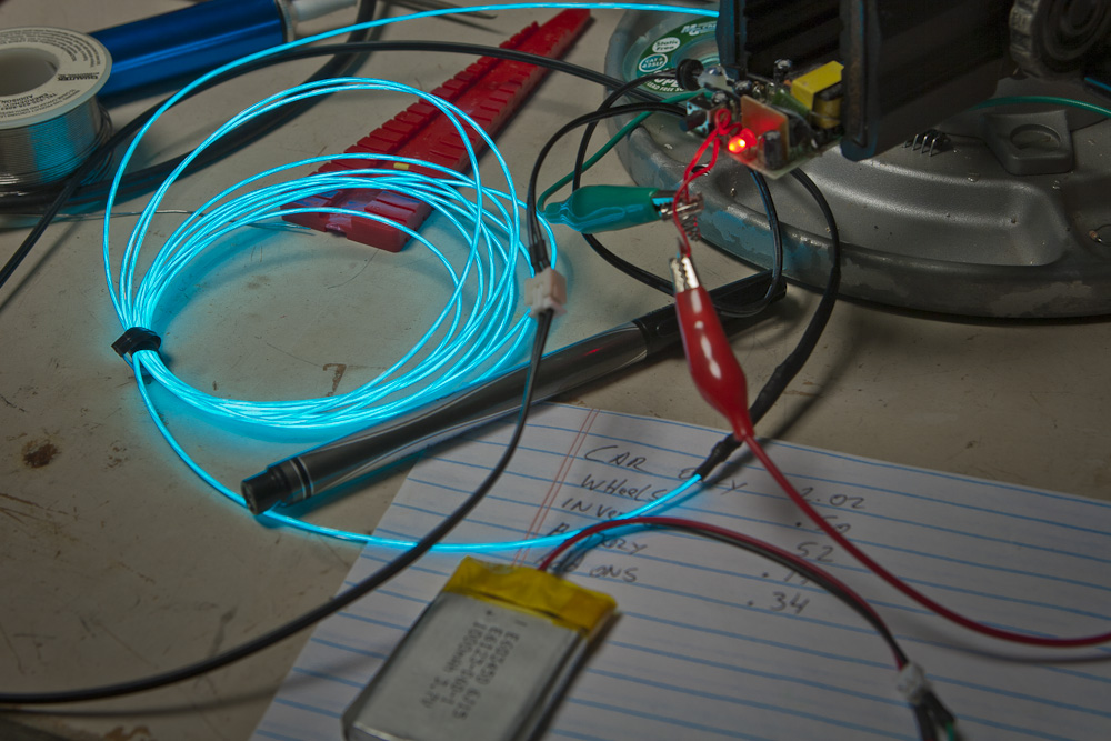
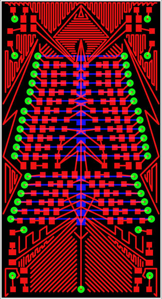
Well here’s the thing… I had purchased this one of their displays about a year ago and never used it for the project I intended it for. I needed to use it because it was stupidly expensive and I didn’t want it going to waste and it seemed to be the type of project which lent itself to perfectly. I used a plastic project box to contain it all. I designed the interface in Draftsight, and let the Shapeoko have at it. I used blue painters tape to help prevent rip-outs and to keep the surface clean. I then used some of my 80’s Tetris skillz to get all the shapes to fit into the box as tightly as possible as there was not very much room. Controller_Closed
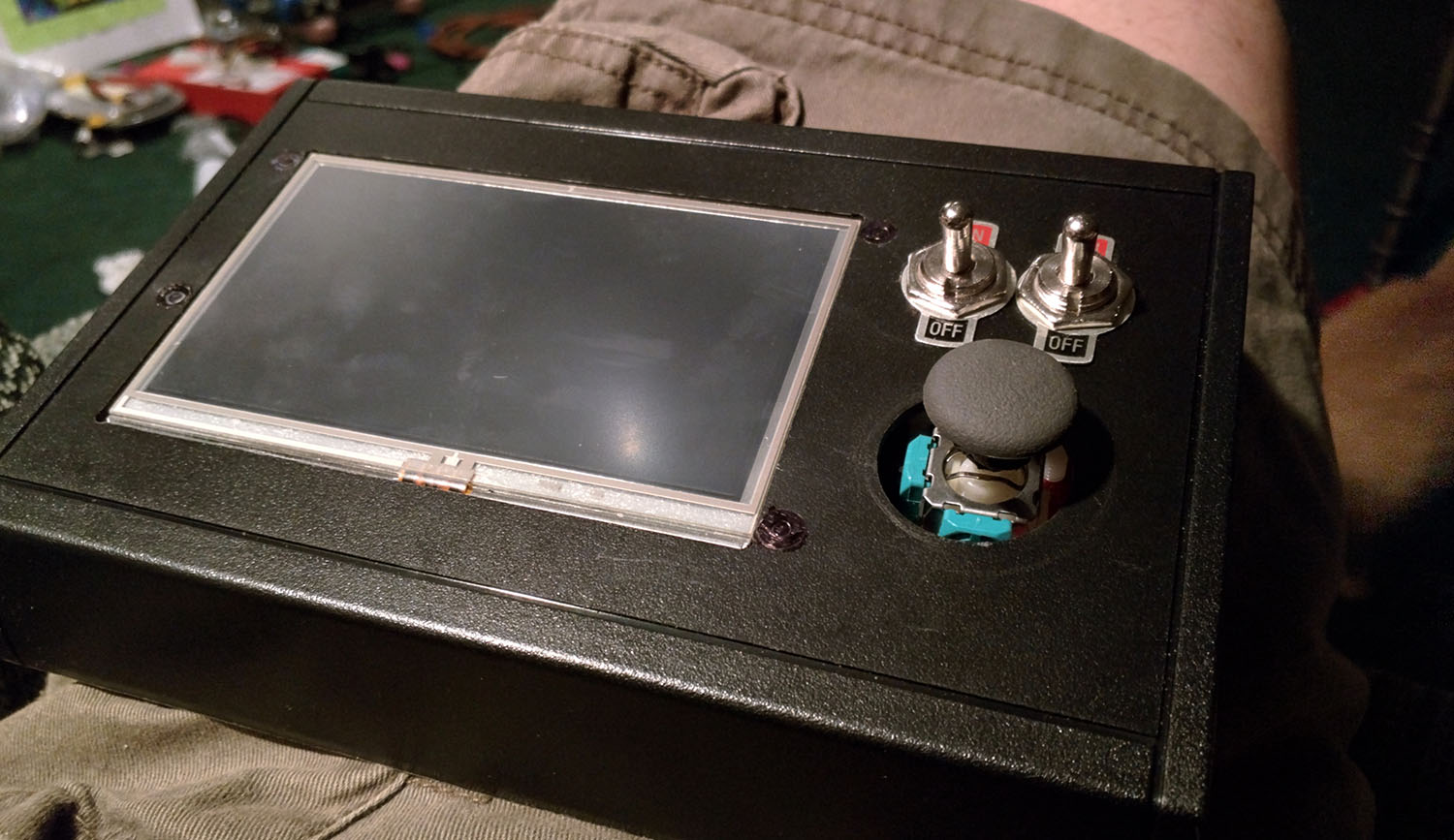
There are a couple of switches. One is for the basic Arduino power and screen, then the second is for the higher voltage for the motors which would be supplied from the LiPo batteries used for RC aircraft. The second switch would also act as an emergency stop in case I needed it. It is an automated device, and I didn’t want to let a robot run without a way of stopping it dead in it’s tracks. Eventually I got it all packaged in the box. The problem I encountered was that updating the code now also required taking part of the box apart. Controller_Innards
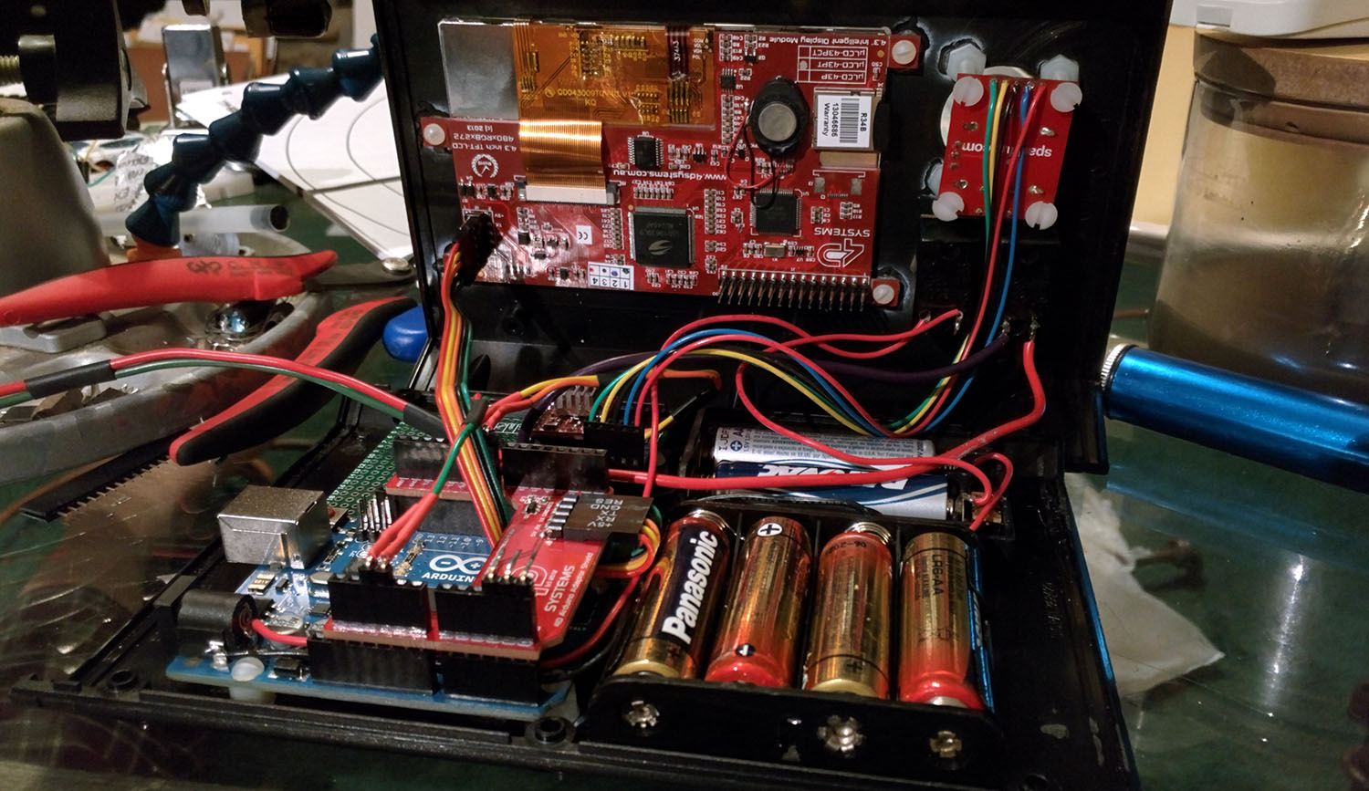
While this doesn’t seem like a big deal, I am really scared that the universe will discover that I had too much mater in one location and result in an explosion of some sort. Taking the box apart just exposes a lot of fragile things to danger, and I once you have come this far, having an accident could result in a lot of time / money trying to fix what usually comes down to a moment of stupidity (I live in a house with a giant golden retriever which has a tail with a striking force of several thousand pounds, capable of destroying most things in it’s path, let alone also the potential spilling drinks and or other liquids one wouldn’t want on their electronics).


Programming

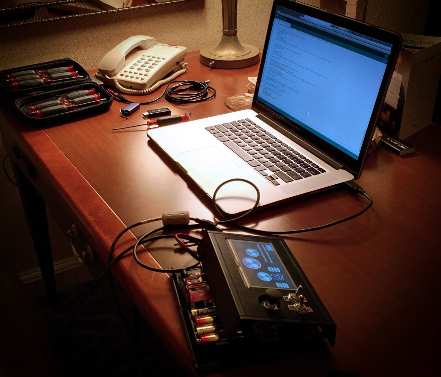
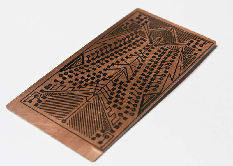
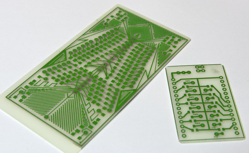
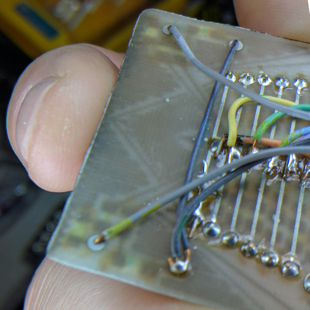
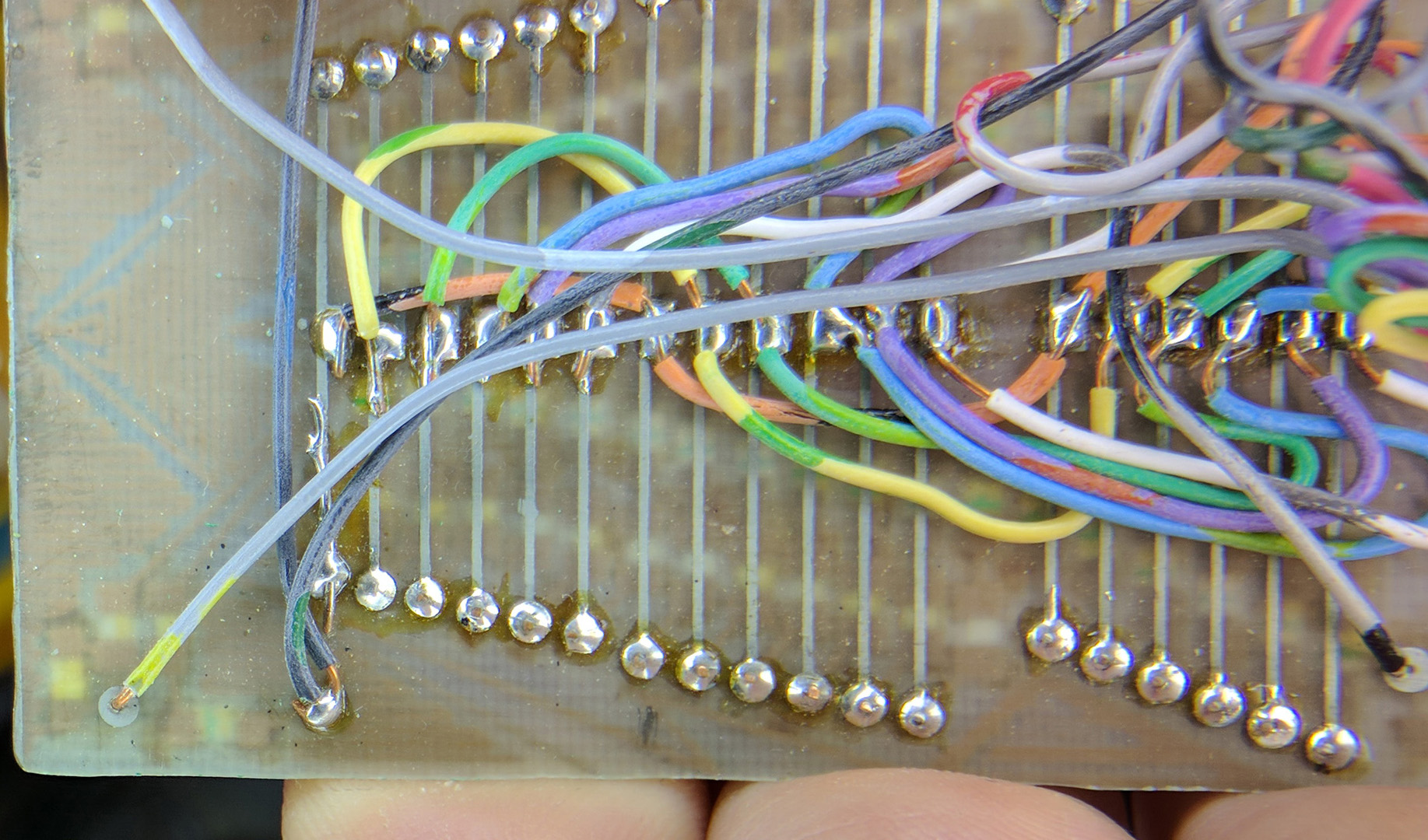
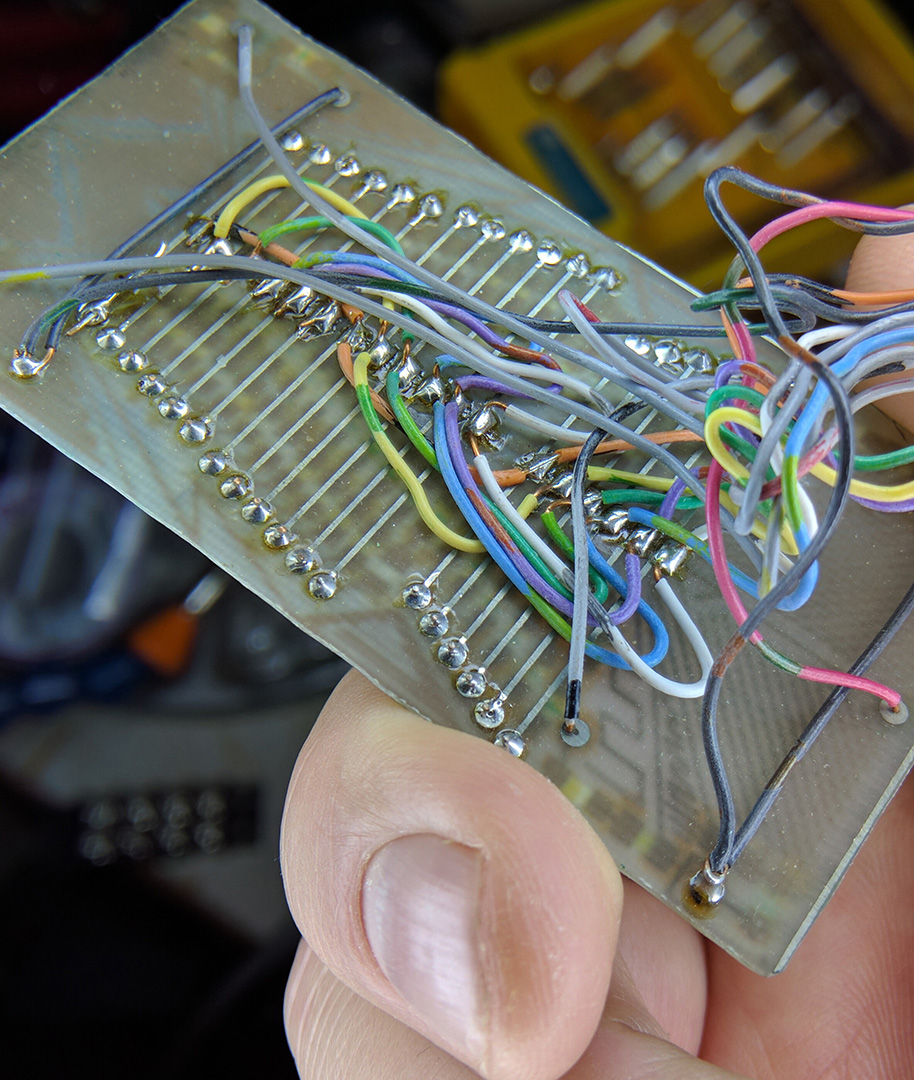
One of the hardest parts of all of this was the programming. I am not a programmer, but I do what I need to do, and learn what I need to learn to make things work. Most of the time, and especially in times like this, I was way out of my comfort zone. There were two sides to the programming. One is the Arduino code itself which is hard enough, but then there’s the LCD code. There’s also the design of the LCD. The LCD is touched which in return sends commands serially to the Arduino. The Arduino then goes to town on whatever I told it to do and sends feedback back to the LCD. The LCD then interprets what was sent, and displays this on the screen. This back and forth pattern must be thought through and as I found out the hard way, you really need to have all your wants and desires planned out. For some reason everything is numbered on the display and if you delete something, or add something above an item which was already there, you can not renumber the items, it just becomes the next in line. This becomes very confusing when you are trying to program some very odd stuff to start with. Many times, you are unsure if it is a coding mistake, or a numbering mistake (which yes, is coding, but not the structural stuff). Everything for the display is loaded onto a microSD card which is inserted into the display. If you are developing for it and trying to get code working, you render the code and graphics onto the card, eject the card from the computer, insert it onto the display, connect it to the Arduino, turn on the Arduino, test and realize that things are not how you envisioned them to be, shut everything down, disconnect the monitor, eject the card, put it back in the computer, choose the windows side of the Mac, go back into the 4D software, tweak, and repeat. But the up side, is that you have a touch screen interface in a fairly short amount of time. Once the touch system and Arduino was sorted out, it was time to get the cameras working with the controller.

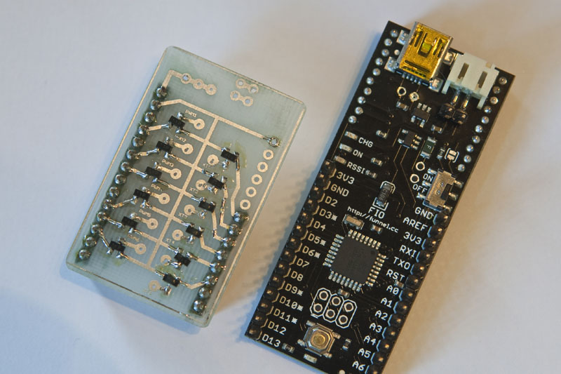
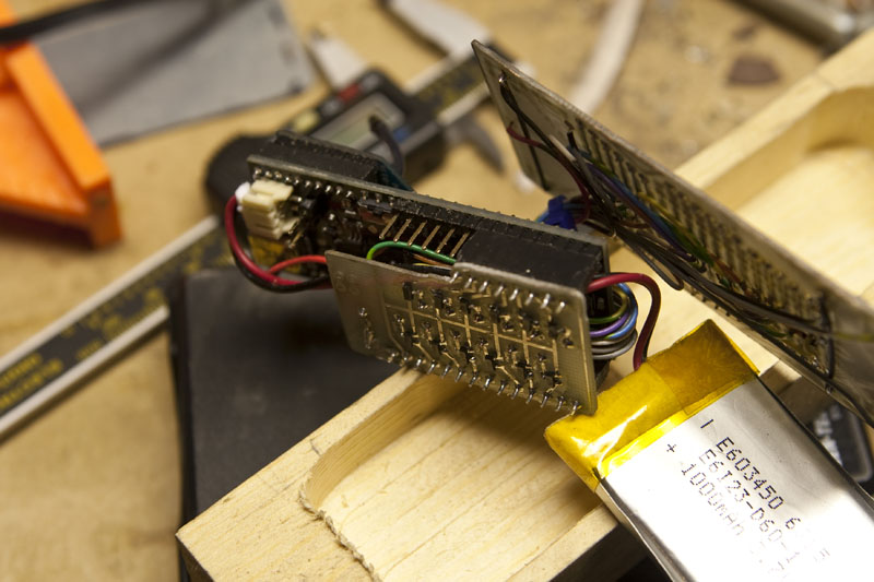
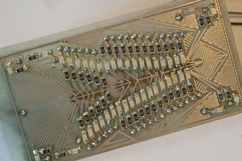
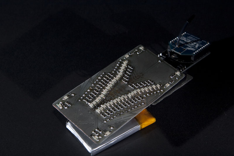
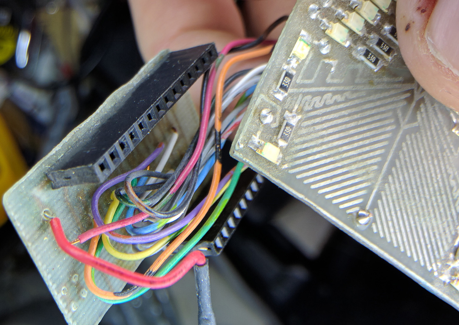
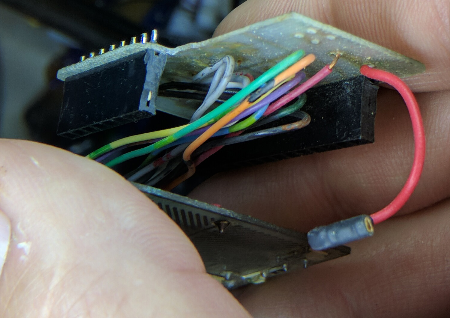
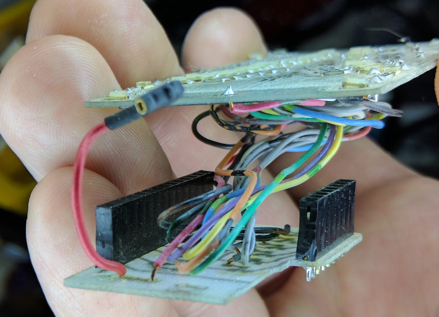
Having worked on my Blackbox Camera Controller (yes yes yes… blogpost forthcoming) several years ago, I was somewhat familiar with how to trigger a camera. Well… I was familiar with how to trigger a Cannon, but not so much with Panasonic cameras. Cannons use a 5 pin cable which works by closing a circuit to trigger the focus, and closing another circuit to trigger the shutter. The I found that the GH4 was not at all the same. It uses different ranges of resistance, or better said, different ranges of voltage to trigger various functions. The resistance was the part I needed to sort out. While I found a couple articles on line, it was a little interesting getting it to work.

Tallulia_TimeLapse_RigSo where does all of this lead us? It leads us to machines taking over the world. Bow to your new masters. When you start to see a project like this come together… there are just no words. You turn the thing on, put in the settings telling it how you want it to behave, and then you press go. After that, it’s just doing what it was told. For the timelapse, I usually have it move, then settle for a second or so (we want a nice sharp image). Then it triggers the camera to shoot an image. Currently it is all set in camera, but changing the length of the exposure would not be difficult, it’s just setting a longer delay between the pin high and pin low. At this point, I could just put the camera into a bulb mode and let the Arduino drive the length. This will be great for things like sunrises where the light levels will change quite a lot. Back to the sequence… Once the camera has fired, it starts the cycle over again. It can be set up for how much distance it moves between images as well. Camera_Plate
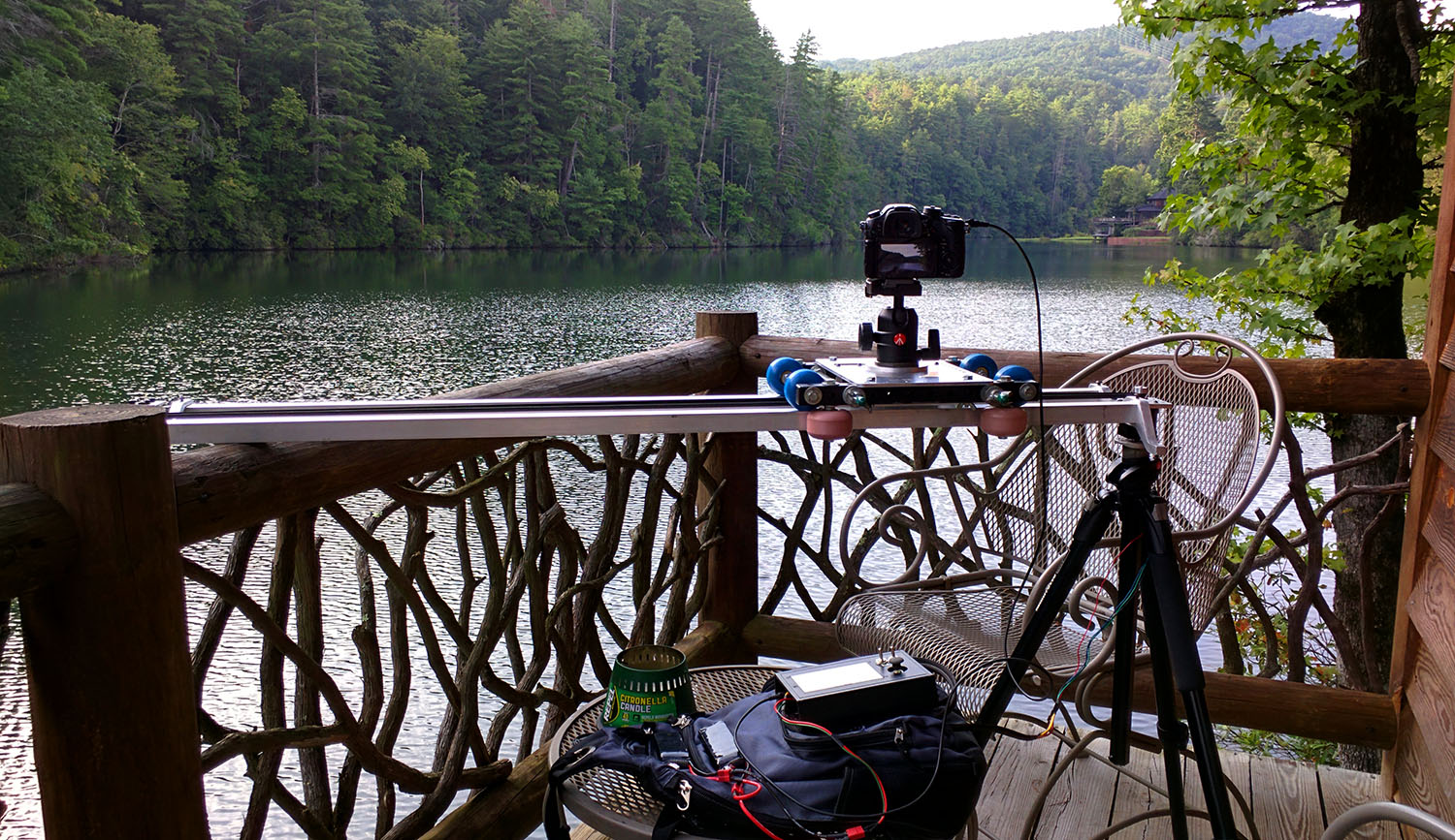
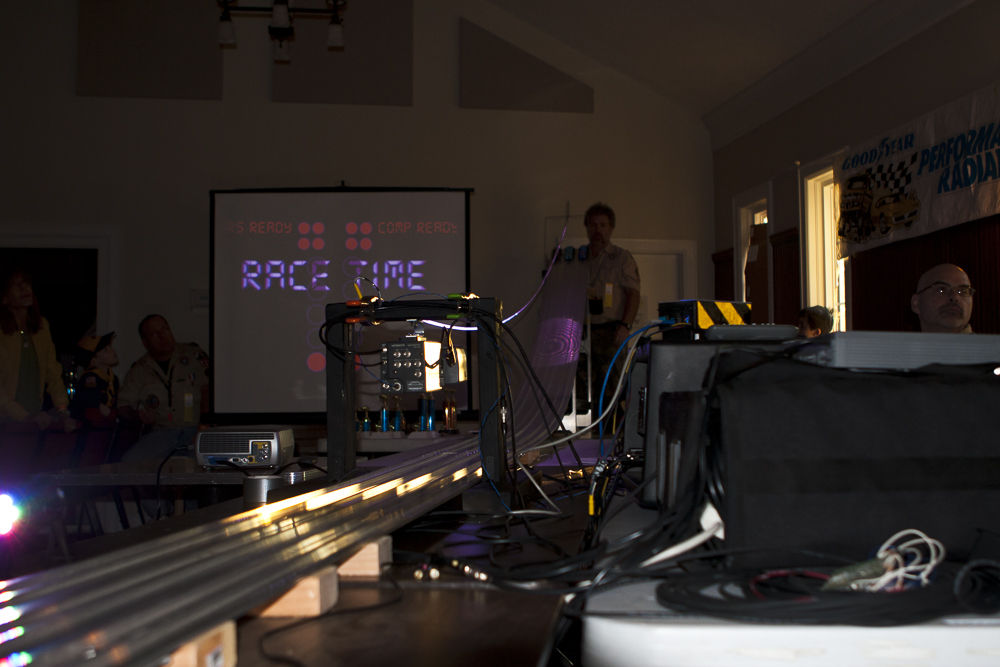
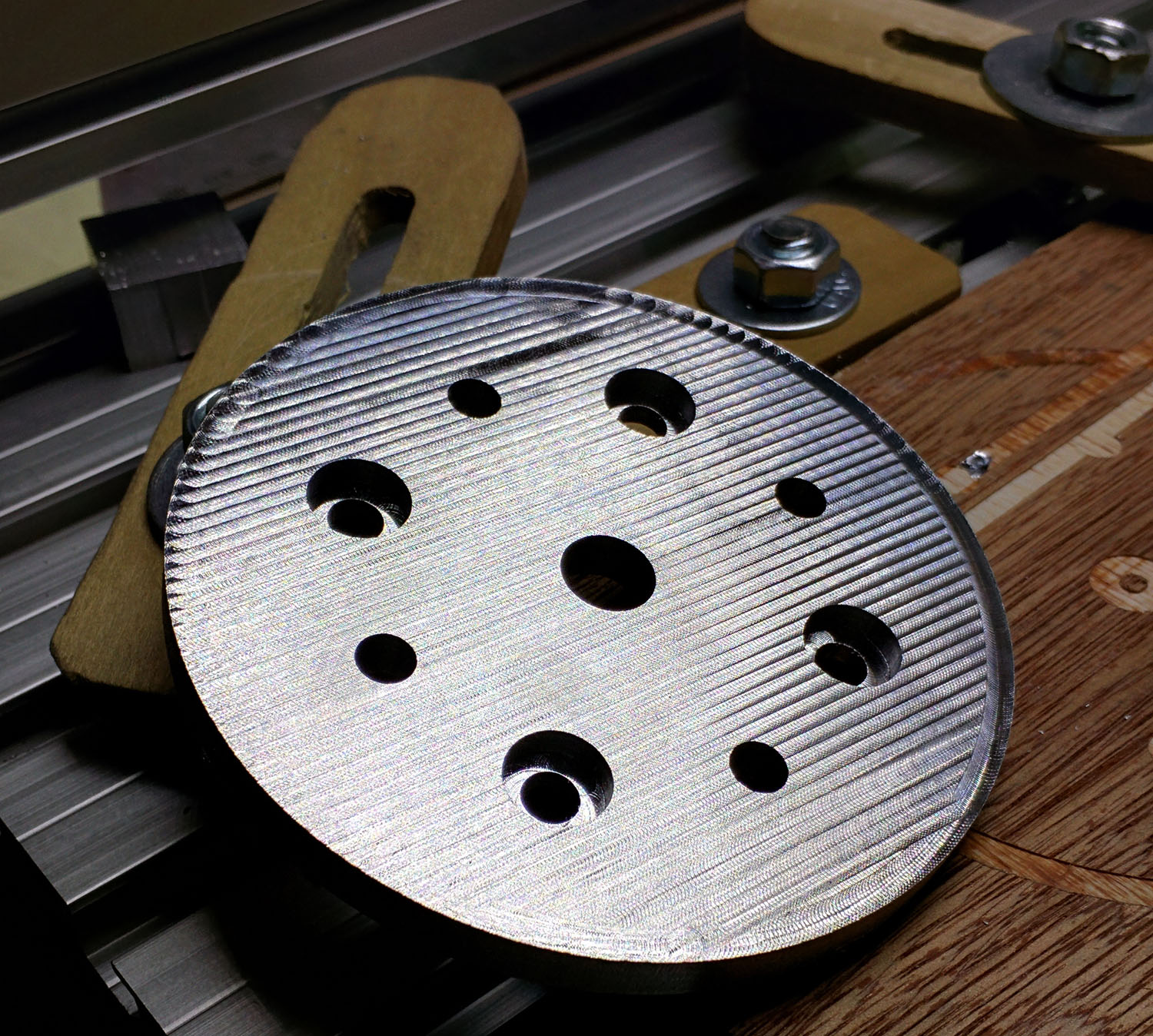
Currently I have the slider working and the pan and tilt are on hold. I built a center disk specifically to take a camera head. I needed to get this up and running for a project we were working on at work. So, I made a major push to get all of this done in my evenings after work. Most of this came together within about a month and I was working on the programming up until about 15 minutes before the first shoot we needed this for. It was a really tight finish. But the video turned out beautiful and our people loved it. After our convention, I was ready for some down time, so what does a technonerd do? Yeah, takes all his camera stuff and heads out on vacation. Here’s a short video I shot from the back porch, again while I was grilling (seeing a trend here?).

 Posted by at 10:47 pm
Feb 042012
 

This year, I took the year off of building a car (not by choice). Instead, I took the helm of the whole Pinewood derby. It may surprise you, but the pinewood team (our pack’s leadership) actually spent a considerable amount of time discussing how we could make the whole PWD a smoother experience. This includes everything from the (pre) registration, to the weigh in, to the event it self. When my son was in his first year of Cub Scouts, we just showed up under the delusion that these things just somehow happen. It was really amazing how much time we all spent working on all the little details. We wanted it to be the most massively fun experience possible for the kids. It was an extremely successful and positive night for all.

Being techie by nature and profession, I have been adding more and more technology each year. My focus has prior to this year has mainly been on the extra stuff. You know, all the techie stuff not related to the track. This year was really over the top.  We were using 3 projectors sporting racing software, custom ‘Christmas tree’ racing software, and Pinewood TV. We used a full on sound system with speakers all over the place to envelop the spectators and bring them deeper into the event. It was probably overkill, but so worth it.

Last year (2011) we had a fairly serious glitch. The racing software would not communicate with the track and the track stopped… em… tracking. It was an all out frantic search for paper and pencils and trying to decide how to run the race off of paper. In reviewing the issues, this came from an incomplete understanding of how the system worked, and the ins and outs of the race software. Being that I was responsible for the running of this thing, I was going to understand it. Ultimately I found that it all came to a dead halt because of 1 silly little teeny tiny switch. When I meter’d it all out, the switch would not ‘close’. In English, it would not reset the track. If the track is not reset, it (the track brain) stops sending information to the computer. The switch was totally FUBAR. It looked fine. It clicked fine. But when I metered it, there was NO internal connectivity either in the open or closed set of leads. Not sure what happened, but it was done. To compound this when I looked at how it was attached to the track, it was loose (floppy loose), and poorly placed. I decided to re think how it was built. I replaced the switch with a new one, and moved where it was located. I made sure that this was a really solid placement. More, there was a lot of mechanical movement in the area where the switch lives. A lever holds the starting pins in place (The starting pins hold the cars in place at the top of the track). When this is released, several fairly heavy springs on the back pull the starting pins causing them to slam down and under the track thus releasing the cars. There was really no need for so much travel, nor that much umph ( from the springs) to get it there. This was solved with a strip of squishy  foam cut down to fit in the little void behind the starting pin block. This reduced the jarring ‘clack’ down to a gentle ‘doof’ as well as reduced the vibration and stresses placed directly on the switch.

I was feeling some pressure to make sure this thing rocked, so I took some time to learn the racing software inside and out. As with most cottage businesses, the pinewood software started because a den dad had a need and a skill set to match. He started writing the software and it has been growing ever since. While looking through it, I found that it was actually very well written with lots of great features. More, I found out that we could have actually used it during last year’s emergency using a points system mode vs. the time based races which we were using. But one can’t change the past. Oh well.  Trying to be prepared in case the worst happened again (which I was nervously confident that it would not), in addition to the software, we were armed with mass preprinted spreadsheets and pencils.

Another upgrade I built last year was the ‘ready’ system to help simple communication between the cogs of the race. When it is loud (crowds of kids and mass excitement), it is hard for the emcee to know if the cars are ready on the track, or if the computer people are ready for the next group to run. So I addressed this by building a ‘ready’ system which would seem natural, but served a very important function. I started by writing a couple of programs in Processing and the  Arduino that would simulate a “Christmas Tree”. Instead of cars crossing a line (telling the computer when it could start) in a real world drag race, I made a button box which sat at the computer position and one start of the track (for the car set up guy). When the computer (pencil and paper) was ready, they would hit their ready button. The same went for the car set up folks. When and only when both groups were set up could the race begin. This was all interfaced through an Arduino into Processing. The races were started by the car set up person. The lights would run the way a real Christmas Tree would run, and when the green lights hit, they would release the cars. This was all accompanied by a ferocious set of sound effects to match. So when they would hit their ready buttons, engine sounds would rev (it was loud and deep enough you could feel it in your chest). The race would start with the Christmas tree lights on the screens blinking down, accompanied by beeps (remember the sounds from the start of the video game Pole Position (if you are old enough to remember) Boop boop Boeeeeeeep!). At the green lights, the sound was of screeching tires and wild engine sounds . When I did the sound design for the audio side of things, I panned the car racing sounds so the sound actually attempted to follow the cars  on the track. A PWD race is really only a couple of seconds long, so I faded the race off into the distance. Lastly, there was an emergency stop button on both button sets. This was for moments where some unforeseen ‘thing’ might pop up.  Either party could press stop and it would kill the sound and reset the display. If the emergency stop was pressed, I used this cheesy VW Bug  ‘meep beep’ noise. In contrast to all this crazy high powered stuff, this rather anemic sounding car horn added a touch of humor. It all worked out very well. The whole thing was put together in a couple of days. It was butt ugly, but it worked wonderfully.

This year I improved on the system quite a lot. I did three things. I built the system to be more rugged, added lighting effects,  and added automated starting of the races so it completely sync’d with the sound. I gutted the cardboard boxes used last year and bought some electrical wall boxes. These were spray painted black (because black looks cooler than blue). Instead of using a standard wall plate for the buttons, I made clear plexiglass covers. I have been talking to the boys about how electronics live all around us and I wanted the kids to be able to look inside the box to see what was making this thing tick. I also reduced the project to a breadboard so they could see how robust a prototype could be (it doesn’t always have to be perfectly printed circuit boards all the time). I found some wonderful reflective yellow and black warning tape at Harbor Freight. This was placed on the boxes which did a killer job of making them look rather menacing. I also added a clear red start button and inserted a wicked bright led so that when the race was set up and ready, it would blink bright red for all to see. The 2 button boxes were connected to the main box via Cat 5, so set up and tear down was super easy.

For the automated starting of the races, I bought a solenoid from Sparkfun and built a little mosfet circuit to run it (also housed in the main circuit box). I used one the ears off of a set of server rack rails to mount the solenoid to. Without mutilating the track (which was out of the question) there was no way for the actual solenoid plunger to reach the release lever (which drops the pegs which hold the cars in place). I made a little whachamacallit to attach to the plunger so it could reach up and wrap around the lever. This was cut out of an old metal computer case (my go to material for all my little metal whachamacallits). I did not want to manage multiple voltages (a 12v  system system for lights, and a 24v system for the solenoid). I found that I could under powered the solenoid with 12v. With 12v it had just about enough push that it came pretty close to releasing the start lever as is, but it was not quite enough on it’s own. The solution came through many of the methods used to get PWD cars to run faster. The movement needed to be slicker and smoother. I used a heck of a lot of graphite on all connective surfaces, and minimized any points of friction by sanding a filing my plunger widget completely smooth. These modifications were very effective and the release was flawless. During the PW derby itself the mechanism only failed 3 times during the 100+ races, and 2 of those were due to user set up mistakes. Sorry for the braggin’ moment there, but rarely do projects work that smoothly. I had to take the moment when I could.

For the lighting, I added a 5 meter strip of RGB LEDs. This was controlled by the same Arduino (actually BoaArduino this year) as the button system. I had to move a couple of pins around from last year as I needed the PWM pins for the LEDs. The track is made out of aluminum which takes light very well. I suspended the strip about a foot above the track. When the ready buttons were pressed, the lights would rev up to match. When the race would start and the lights would blink in synch with the sound which would be in synch with the screen. When the lights went green on the screen, the track would go ape dooky with a strobe of green and bright white. Then when the racing was finished, the lights faded down to red, then down to dim red. If an emergency stop was called, the lights would sit and blink red on and off for about 4 seconds like hazard lights.

Mentioned above, we also had TV. I brought in a small video switcher (straight cuts only, nothing fancy). I made a 5 minute looped graphic video of racing flames, checkered flags, and a logo. This would play on the screen in between races. There were 2 track cameras. One pointed up at the starting line. This was suspended right over the track on a sort of wood bridge that I made. This was a great shot. You could see the race start and then the cars would fly right at, then under the camera. the camera lens was sitting just 2 inches above the maximum height allowed for cars. (The 2 extra inches was so that I would not get yelled at by some parent who thought that I had somehow had lost their kid the race. While the PWD brings out some of the best qualities in a kid, it brings out some of the worst in some parents (Just sayin’).  The second camera was placed at the end of the track to catch the cars as they went through the finish line. My son actually did the video switching for the night and I must say, he did a great job.

You can not pull off something like this without a great team, and man, all of our Pack 553 leaders stepped up and helped out wherever needed. We started the load in and set up at 10am (the morning of the event), and finished about 5 minutes before it started. While everyone was working hard, no one was rushed. We just did everything we could while we could. After the PWD, it came time to tear down and pack up the car. I will tell you that everything in that room (aside from the track) fit in my Prius. Granted, it probably would have popped if I poked it, but it handled the load.


 Posted by at 6:42 pm
Feb 222011
 

As I have said more than once, I was an 80’s kid. As you know, Tron Legacy came out. While I was a little disappointed in the story, I was totally in love with the art. It was beautifully done with so much attention to the little details. If they paid as much attention to the story, it would have totally rocked… but I digress… I wanted to make this years pinewood derby car in the styling of the new movie.

I decided to take a different approach to the building of my car. Instead of starting from a block and working down, I started by sawing the block down to a thin slab and adding to it. Using thin pieces of wood, I carved each piece of the car with the coping saw and / or razor knife. The caliper helped a lot. The wood is soft enough that I could mark the wood easily. I used super glue to keep the weight down. Then I used wood filler to fill in the the cracks between the pieces.

The overall design is something between an F-16 with no wings and a Comaro. The jet intake, rear, hood grill, and the front grill were from an old set of computer speakers. They were of course rear lit as well. The hood was to have plexiglass inbedded in it, but I could not get the fit to not look chunky so the idea was scrapped for the metal.

In the past I have used screws to hold little things like this together. This year I wanted to make it easier to access the guts. I used a little neodymium magnets to hold the top onto the bottom of the car. The only thing I do not like is the bump in the middle of the top piece. There was supposed to be a rear spoiler, but I did not have time to built up the back end to add it.

I thought through many different ways to achieve the glowing linage. I bought and experimented with everything from science grade glow in the dark paint, back lit plexi, UV reactive paint with UV LEDs, and eventually settled on EL wire. It is what was used in the movie for the costumes. It was the best look for the size. I had to come up with a way to fit the inverter in the car, be able to turn it on and off, and most importantly, how to power it. I opened the case that the inverter came in and hacked the board so I could move the batteries and switch to the middle of the car. For weight and size reasons I chose to use a small LiPo battery. The last thing I added was 0805 SMD UV LEDs for ground effects and head lights. The effect was very slick. Another nifty (and unintended) effect was that the inverter has a high pitched whine to it. In addition to looking very electric, it also sounded very electric.

Triumph and agony…
Sometimes when you work on things for too long, you loose your mind. This can be a dangerous thing if not to yourself, then to the object being worked on. I spent a lot of time priming and painting the car so it had a near ‘real car’ paint job. I mean, I spent a stupid amount of time painting, sanding, painting, sanding… Then it’s time to put the wheels on. If you have ever built a pinewood derby car, you know that this last step is the time where most cars get damaged, and this build was no different. It was 3 am(ish) and I had to finish the thing as it would be checked in the following day. I put the front wheels on first and they went on without issue. The third wheel went on without issue. On the 4th wheel, as I was tapping the nail in, I heard ‘CRACK’. I put my head down on the workbench and let out a big sigh, pretty much knowing what had just happened. After about 30 seconds or so, I decided to look at what the damage was. The top of the car (in the back) had caved in. This was not something that could be repaired easily, or quickly. I had to get up for work in a few hours and it needed to be turned in right after work. There was no time. I chose to get it at least track worthy. I glued the heck out of the broken area. To add insult to injury, when I picked up the car to look the damage closer and the car fell out of my hands and landed beak down. While it did not break, it added another nice little ding to the killer paint job. There is a lesson in here somewhere… I am not sure what it is yet… but it’s there  ;0) .

 Posted by at 8:09 pm
Feb 252010
 

So, it was pinewood derby time for the Cub Scouts again. My son’s pack has a race for the adult kids too. I had been plotting my car since last years races. I wanted to really light the thing up.  Last year I had working head and tail lights, but this time I wanted bigger and better. I was just not sure what form it would take. I had considered many options. The most predominant idea was using an accelerometer to change the light settings based on force. The problem was that I wanted the lighting to stay very minimal until race time so that the surprise factor would be maximized. I was leaning heavily towards the Arduino Pro 3v due to it’s nice and tidy size. After more thought I started heading away from the accelerometer and started thinking about using an XBee to control the Arduino remotely.  Then while shopping at Sparkfun one day, I stumbled upon the Funnle IO board and that locked the plan together.

Funnel is an Arduino based board, with the added benefit of having an on board Xbee socket. Plus it is tiny, has a 3.2v line in (for  LiPo), and a LiPo charger onboard too.

I ordered the stuff from Sparkfun and started designing the circuits. The mental picture was to make 2 stripes that ran down the sides of the car. These would be able to blink, pulse, fade, and ripple. Then on the 4 corners I wanted to have a very bright strobe light effect that would strobe at about 1 pulse per second. The idea was something like a jet preparing to take off and the taxiing lights. I put together a breadboard mockup.  I decided to use the 6 PWM outputs for the stripes. This way I could make them flow however I wanted. I worked on many different ideas for making a slow PWM roll. I finally found that to make the lights really roll along, I needed to have more than one set as the rolling motion is much more pronounced when repeated in a longer strip. The thing started to take form.

I decided to use 3 sets of 6 LEDs on each side, but instead of running down the sides, they would actually sit on top of the car like some evil menacing engine. I did not want big bumpy 5mm LEDs all over it (which actually might just be cool), so I went with surface mount. All the LEDs and resistors are 1206. 36 LEDs at 20ma each would easily exceed the max draw for the Funnel, so I built a driver board to take the load off of the FIO. The driver board was nothing fancy, just a few small 2222 transistors (sot-23).

One thing I had a great amount of fun with was designing empty spaces on the board. Once the board was designed, it was quickly clear that though functional, it was hardly cool looking. There was a still ton of blank space, so I decided to decorate the PCB. It was arts n crafts time with Eagle Cad. So, I spent a couple of hours just playing with shapes. By about noon the next day, I had the board etched, and all soldered up, and was ready to start testing. I uploaded the code to the funnel and started to play. I had some problems with one the channels of strip lights. It turned out to be a transistor that was not completely seated on the board. It looked soldered, but when I heated it up and pushed down on it, it just sank. It was a quick fix and it worked great from there on out.  I made sure that the xBee was working, but mainly stayed on the ftdi cable during the remainder of programming and testing.

After designing the car, I needed to route out the innards where everything would fit. This was a little easier on paper than it was in wood. Eventually, it started to come together. Making a long story short, I got everything together and it worked great. This was my first real Xbee project. I really liked that I got feedback from the car which was sitting like 60 feet from me. Of course I had to program the Arduino to do so. All I needed to do to trigger an effect was just type a letter into the serial command box in the Arduino IDE. I had about 14 different things I could have it do.

Edit: (News) – My car is on Sparkfun’s Front Page!!! Call it my Andy Warhol 15 seconds. :0)

Edit: (Clarification) – No, I am not employing a “joule thief” circuit in the car. We get to name the cars, and I felt that the name fit. Some folks have asked if this is an “official scout issued” PWD kit. Yes it is, but I used 2 kits. The finished car is legal weight, but just scraping by. The wood weighs almost nothing as it is more or less, a shell.  When I weighed it after finally getting all together, it was over by quite a bit. I had to hollow out just about every place that was thick enough to be drilled. I avoided the spaces right around the wheel grooves as I did not want it to bust through during the race. If you look at the front picture on the video, in the reflection in the glass you can see where I had hollowed out the sides. Drilling a car that was already completed was a pucker factor of about 12. I really thought I was going to blow out one of the sides. But even that was not enough, when it raced, it did not have the left screw in place as it pushed the car over the legal weight of 5 oz..

Eagle Boards, Schematics, and Arduino Code


May 062009


We had a staff meeting at work. The topic of discussion was Relay for Life. Our department usually participates in some way. This year, there was the challenge of making a car out of boxes which would be carried around the track at midnight in a race. requirements were simple. It had to make it out of a box (duh), and it must have headlights. Seeing mass geek potential, I volunteered to build the car. I am not one to go to if you just want dirt simple.

I started to plan a rugged, heavy duty, off road kind of thing. Soon after we got a fairly massive UPS. The box was perfect. It was this crazy heavy duty cardboard. There was also this wonderfully shaped packing foam in the box, so that got grabbed as well.

One of the women who would be carrying the car is a cancer survivor. So, this was a custom build, just for her. She said that her car was going to be pink. Pink? Really? um… ok then. She said that we could also have purple trim if we liked. I decided on duct tape, and gaffers tape for the construction and vehicle color. Inspired by the shape of the foam, I set out to build her a hummer. A BIG PINK AND PURPLE HUMMER!

For the headlights, I wanted to go over the top. I decided that this thing needed a operational lighting system. Sure, we could throw in some flash lights, but I wanted bigger, and far brighter.

I have been experimenting with white LEDs for a camera flash system I have been working on. I decided to make panels of LEDs for the head lights. But really, how safe would a car be if there no brake lights, and blinkers? So, I made some LED panels for the rear too with real working blinkers and brake lights. This was all connected to an Arduino (Boarduino) through some FETs. I used 2n2222 for the left, and right blinkers as there was not as much amperage to worry about (Only 16 LEDs). There are 40 LEDs on the each brake light and and 40 each on the headlights. I got hit in the eye a few times with one of the head lights, and it was a wee bit painful. The brakes are each on PWM pins on the Arduino so that they could be slightly lit (because they are on when you turn on your headlights, right?), but then have the ability to go full bright during left and right blinking, as well as braking, all of which was controlled from a little button box. On the back wall of the car I made a LED ribbon out of pink LEDs. My initial intention was to do a 4 channel chase with the ribbon, but there was just not enough time.

The Relay night came. They took the car out to the track. They kicked on the lights and the 80 10,000 mcd white LEDs in front really lit the place up. They had a good time racing the pink beast around the track. Our car won for design.

Sep 112006
 

Power cord Hole
The first order of business was putting in the monitor. Looking back on thing putting in the monitor should have been one of the later things, but…oh well. Live and learn. I realized early on that I forgot to drill a hole for my power cord. Doh’. So, Being very careful not to goof up all the paint, I strapped a board to the bottom of the cab and drilled my power cord hole. This was a painless procedure. Also, I ran the vacuum tube through the coin door hole. Anytime I had to drill, I would turn it on so all dust was immediately sucked up (except for the power cord hole). Then I put in the smart strip.

Aux Power Supply
I decided that I wanted car speakers and amp for a little stronger audio source. I also wanted to use cold cathode lighting. I did not want to run either off the computer PS, so I installed an auxiliary PS. Seeing as I would not be hooking this up to a computer, I did away with the Molex adapters,then trimmed and sorted the wires. I capped each line with heat shrink that I was not using.

This way the feeds would be there if I wanted them for future add-ons, but 1. Would not be a safety concern in the mean time and 2. Would be neater wiring in the cab. You will notice that the 2 lead sets that ware coming off to go to the amp and the lighting also have a green and black pair. I soldered these together and heat shrank it to the bundle. This way the PS is always on as long as there is power. I shortened the 2 PS power cords to about 1 foot.

Securing the PS’s
I did not want to make a custom bracket for the 2 power supplies. So, I took the PS apart and used the bottom to be my connector. I used a Dremel to cut tags on the PS. I bent them out flat and pre drilled holes in them. Then after I drilled pilot holes on the cab I attached the PS. Rock solid!!! I then attached the amp to the right side of the cabinet (inside left).


Coin Door
In the evenings my kid likes to play outside. Duh, it is summer and kids play outside when it is nice out. So, I used that time to work on out door cab projects. I think I mentioned it before, but I got a over under coin door at a not so near by pinball dealer. When I went to get my back glass for my Black Knight, I was a sawed off dynamo being as a TV stand. I asked if he would sell the coin door out of it. He said I could have it for $15 if I pulled it myself. SOLD!

I do not know where this thing had been but if was covered in crap. The coin mechs had to be dremmiled clean with the soft wire brush. This stuff was stuck on. The mech holders had some mystery goop on it. I became almost OCD about cleaning my hands after dealing with it. I feared that I was handling someone’s puke or worse. But hey 15 bucks is 15 bucks eh’.

I wound up taking the entire thing apart. I took a stiff wire wheel doors and frame. Afterwards I sanded everything nice and clean. I opted for the Rust-o-lium Satin instead of the original hammered look. It came out really slick.

Motherboard
I had a computer that I had set aside for the project. When I went to set it all up the computer decided it would rather kill it’s self, instead being involved with this project. I was really bummed. My partner in arcade crime, Neal, had a Celery 1.8 GHZ that he was not using that he donated to the cause. Woo hoo! Nice case too, but the computer was destined to be inside the cab caseless.

When removing the mother board I took lots of pictures so I would remember where to put everything. I have to tell you, having a camera on my phone is a wonderful tool in situations where I forgot my real camera. I also made a map of the screw holes so I would not forget any. 12 screws. I was not sure if I needed all of them, but it would seem that is I was adding or removing IDE lines or power or video cards, not having all the support might damage the board, so I decided to do all 12. The motherboard would not sit flat against the wall so I found some 1/4  in nylon stand offs at the Home Depot. I will just say for the record that mounting a motherboard to the side of a cabinet, maintaining level, and getting little stand offs on with the screw in it while balancing between the monitor and the floor of the cab was a major main in the posterior. Remember the comment about perhaps putting the monitor in later? So, I screwed one screw (with stand off) in the center top hole of the motherboard. I leaned in the cab on one elbow (left) got the stand off in a pair of pliers in my right hand. I put the level on top of the motherboard, found maintained level with the left hand, put the stand off behind the motherboard with the right, then pushed down on it with the right while grabbing the screwdriver with the left, fidgeting to get a screw and placing it through the hole and finally tightening it down (which was the easiest part). Needless to say, I did not take a picture of this process.

Hard Drive Mounting
While I was taking the PC apart, that there was all sorts of usable metal bits in the case. I decided to use this stuff for many parts of my cab. I dremeled off the hard drive cage (it was tack welded in there) and modified it to be screwable to the cab. I put some holes in it, bent it, painted it, put it in the cabinet, added the hard drives, and screwed them in. I did the same for the DVDr Drive. When I got the DVDr installed, I realized that the lip of the door stop was right in front of the DVDr. I decided to try to open the tray. To my relief, tray misses the door stop lip by about 2 or 3 mm. Whew.

Menacing Little Blue Light
I have always liked how Macs have the power light that slowly just fades on and off. I decided that my cab needed a similar thing. I pulled out the ol’ RadioShack project books and started looking for a schematic. I did not find exactly what I was looking for so I set out to create my own recipe. After experimenting for a while, I finally had a good balance in fade timing. I dug through my old electronics stuff and pulled out piece of perf board and began constructing. About 3 hours later I had a working pulser. I put the circuit near the coin door as my main power button is mounted near by here too. I ran the little wall wart PS to the outlet on the smart strip that is always hot.

I love it, it sort of gently taunts you. Come here… Play me…

The On buttons switch was then wired to the motherboard power on connection. I used the connector that was originally attached to the motherboard switch as it had the header receptacle already on the wires. I soldered on an extension and attached it to the button. It was easy and it works great.

Control Panel Wiring.
This seems to be one of the most time consuming parts of the entire build. I had 32 channels of LED lighting, 2 – 49 way Joysticks, 21 buttons, , a track ball, track ball buttons, USB for all the interfaces, plus a custom lighting wiring adapter that would feed the rest of the cabinet (coin door switches, LEDS…).  I started with the LED wiring. 5 buttons will be using RGB LEDs while the rest will use Blues except for 3 reds at the top. After all the Push Buttons, Joys, TB, +Interfaces were in, I realized that there was a significant shortage of real estate available for clean wiring. But I set out to do just that. I decided to use wire looms I bought from Frys. I bought a roll of 1/4 in and got a package that contained a variety of different sizes. Every time there was any distance between source and destination, I would loom it. This way all wires would be both secure and tightly bound together.  I did the player 1 LEDs first. I tested each LED Before and after I added them because I did not want to get to the end of all the looming, heat shrinking, and soldering to find out that I had a problem somewhere. I build a little LED tester a few years ago which helped. I put heat shrinking at every solder point so there would be no shorts at some point in case something shifted. I decided to put all the resisters by the LEDWiz so I had only clean wire in the tight spaces. This seemed like a good idea, but as I soon learned, it also got very tight around the LEDWiz.

The RGB LEDs were set up with RG&B wires for easy tracing. I did all the LED and PushButton wiring in my living room while watching TV at nights. I have to say my family was very supportive in this trying time. (I sort of made a big mess). Little snippets of red, yellow, blue, green, black, and yellow wires everywhere. After Player 1, I did players 2 then the utility buttons (coin up, P1, P2, Esc, and Pause). This took several nights and mornings (before work).

Then I moved onto the push button wiring. After the LEDs, the PBs (Push Buttons) were a piece of cake. All the PBs were wired with yellow wire so they totally stand apart from the LED lines.
I talked to Randy T from Groovy Game Gear and asked if he saw any problem with me making the mouse buttons also connect to the GPWiz49s shift key. He did not see a problem. So, once in MAME, being that I would not be using the mouse buttons, the shift keys come into play. Buttons 1-5 on both P1 and P2 can all be shifted. This is great for quickly changing volume without having to leave MAME.
By the way, if you are someone who does a lot of soldering and feel that helping hands do not really help as much as one could hope for should check out the Panavise sets. I got one on e-bay for like $15. They can be like $85 at a store. But you can clamp a circuit board or LED or anything up to 9 inches and rotate it in just about any position. It is a GREAT TOOL!!!

Track Ball
I hooked up the LEDs for the Track Ball. This was not a difficult thing. Wire, wire, snip, snip, solder, solder, heat gun, know, what I mean nudge, nudge, wink, wink, snap, click, know what I mean…He asked him knowingly.

Cable Tracks
I wanted the inside of the cabinet to be absolutely clean once it was finished, so, I installed cable tracks all the way around the bottom of the cab. I also have one track going up the left (inside right) front panel (coin door panel), and one track running up the back right inside of the cabinet (near the door) which takes all wires up to the speaker board area. All wires and cables travel through these tracks. There are no loose wires wandering aimlessly around the cabinet. This has helped during times when I would need to climb in there to work on stuff.

Speaker Board Wiring
I wired up the Speaker board via DB9 connectors. The connectors connect at the back of the cab for easy repairs (if needed). Also if I have to remove the monitor ever, the wiring needs to be disconnected in order to get the monitor frame out. The DB9 connector went to +12 and Ground (From Aux power supply), Speaker L & R, and lastly line 32 from the LEDWiz and a LEDWiz Ground. In each notch below the speaker holes, I placed a red LED. My speakers have a metallic silver grey color. This makes them light up really nicely. The cool thing is that they are not so bright that they are distracting, but just subtle. I like it. After everything was wired up, I put it in the cabinet. Wow, another piece in place and another step closer to being done.

LEDWiz
At this point I could no longer stand it. I had to fire it up and try out the LEDWiz. I played with it for several hours. I programmed many sets of animations and started to get the hang of it.

Marquee Light Board

I used a piece of hard board for my light board. First I measured out where I wanted my hangers. I drilled out holes on the hardboard. I put the L brackets on and attached them through the hardboard. Then I put the hardboard in the monitor hole and marked where I needed to place my pilot holes (I had to take my speaker board down first). I drilled my pilot holes. On the hardboard I used Foil Tape to coat the surface. This way as much of the light as possible would go out the marquee, not get absorbed by the light board. I drilled wires for cold cathode to reach the inverters. May sound stupid, but I did not even want the inverters sucking up light, so I put them on the back of the light board with Velcro. I wired the inverters to the 12V feed and then the cold cathode tubes to the inverters. One thing to mention. I snipped the on off switches off of the inverters. I always wanted the marquee lights on if the cab was on. Plus I could not see unscrewing the entire sound board / light board set to turn off the Cold Cathode tubes.

The morning after I put the CCs on the marquee light board I noticed that the cheap POS foam tabs used to stick the CCs onto the light board with had fallen off in several places. I decided that this would not do, so I replaced all pads with the same heavy duty Velcro that I used for the CP top.

Marquee
I had used MAME Marquees for a few marquees in the past. Scott always did a bang up job. My only gripe is that when lit, the marquees look a little washed out. Plus you can see the paper texture through the print. Now, read this clearly, I am not saying that his products are bad. Actually, I feel quite the opposite about his stuff. I used him for my CP which I think totally ROCKS! I decided to go a little further for my Marquee. So I found a company (Megabytes Digital) which makes the translites for movie posters and restaurant menus. Actually they are the company that does all the translites for all the Chick Fil-A restaurants. This stuff is not printed on paper, but on a film type material using a milky substrate. Basically it is plastic, white on the back, color print on the front, and lit like film, so it is made to take light. So the colors are rich and very detailed when lit. I LOVE the way it turned out. It is thin, not like the old marquees, so it must be protected.

NOTE: As I understand it, MAME Marquees no longer uses just standard printing. It is apparently very similar to what I got from Megabytes.

Marquee Installation
I bought a piece of plexi for the Marquee. I cut two identical pieces so I could sandwich the marquee translite in between them. I made a holder out of 2 pieces of ¼ in. angled aluminum. First I put in the back piece so I could get it nice and straight. Then I put the 2 pieces of plexi against it and put up the second piece of aluminum and marked it. I wanted to get it as tight and close as possible. I set down the loose bits and predrilled the holes. I held up the plexi once more and screwed down the second piece of aluminum. It was a tight fit, but it was strong enough that everything held into place without the use of the marquee retainer.

At this point I had to make the leap and take the plastic off the plexi. I decided to try an experiment. When you work with electronics, sometimes you have to wear an anti static strap. This is to dissipate a static charge so you don’t fry sensitive components. I tried this in reverse. I strapped the marquee plexi to the strap then to me. My hope was that I would absorb the static charge generated by the plastic removal. I’m not sure if it really worked or not, but they were not covered with dust after I removed the plastic. I quickly placed the marquee down, put the plexi on top, trimmed the marquee, put the back plexi on and mounted it into the grove mentioned above.

I placed T-nuts across the top edge of the speaker board. These are for the marquee retainer. I got some hex screws and sprayed them black. I measured the retainer and cut it to length. I drilled the holes and installed it on the cab. I like the hex nuts as they give a little more authentic look to the retainer.