
So, it was pinewood derby time for the Cub Scouts again. My son’s pack has a race for the adult kids too. I had been plotting my car since last years races. I wanted to really light the thing up. Last year I had working head and tail lights, but this time I wanted bigger and better. I was just not sure what form it would take. I had considered many options. The most predominant idea was using an accelerometer to change the light settings based on force. The problem was that I wanted the lighting to stay very minimal until race time so that the surprise factor would be maximized.  I was leaning heavily towards the Arduino Pro 3v due to it’s nice and tidy size. After more thought I started heading away from the accelerometer and started thinking about using an XBee to control the Arduino remotely. Then while shopping at Sparkfun one day, I stumbled upon the Funnle IO board and that locked the plan together.

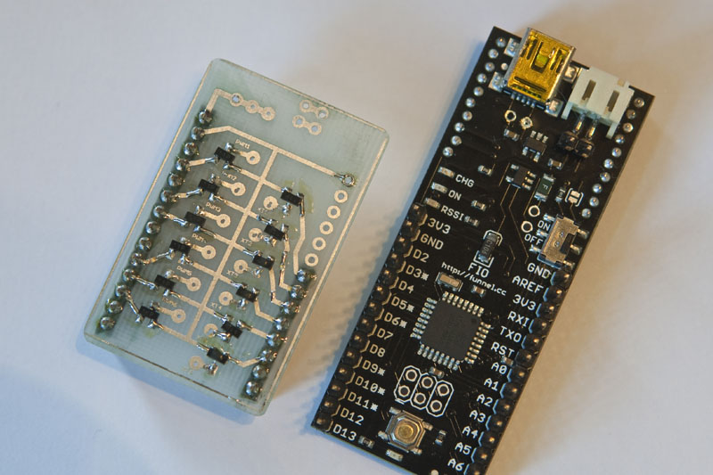
Funnel is an Arduino based board, with the added benefit of having an on board Xbee socket. Plus it is tiny, has a 3.2v line in (for LiPo), and a LiPo charger onboard too.
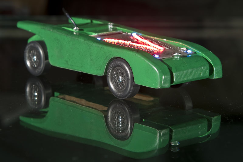
I ordered the stuff from Sparkfun and started designing the circuits. The mental picture was to make 2 stripes that ran down the sides of the car. These would be able to blink, pulse, fade, and ripple. Then on the 4 corners I wanted to have a very bright strobe light effect that would strobe at about 1 pulse per second. The idea was something like a jet preparing to take off and the taxiing lights. I put together a breadboard mockup. I decided to use the 6 PWM outputs for the stripes. This way I could make them flow however I wanted. I worked on many different ideas for making a slow PWM roll. I finally found that to make the lights really roll along, I needed to have more than one set as the rolling motion is much more pronounced when repeated in a longer strip. The thing started to take form.


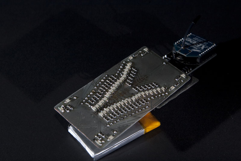
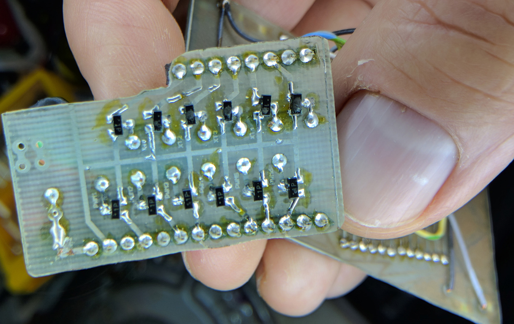
I decided to use 3 sets of 6 LEDs on each side, but instead of running down the sides, they would actually sit on top of the car like some evil menacing engine. I did not want big bumpy 5mm LEDs all over it (which actually might just be cool), so I went with surface mount. All the LEDs and resistors are 1206. 36 LEDs at 20ma each would easily exceed the max draw for the Funnel, so I built a driver board to take the load off of the FIO. The driver board was nothing fancy, just a few small 2222 transistors (sot-23).
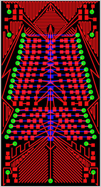
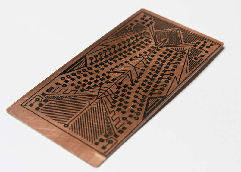
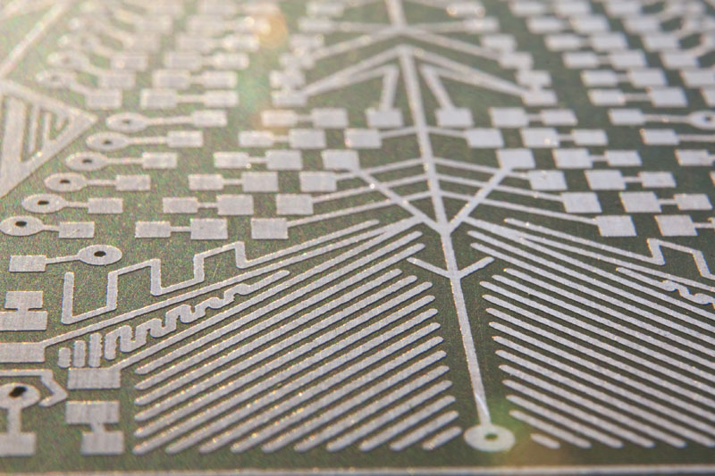
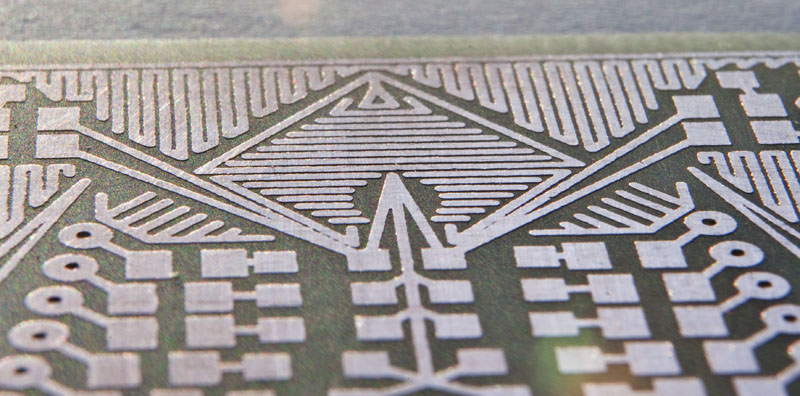
One thing I had a great amount of fun with was designing empty spaces on the board. Once the board was designed, it was quickly clear that though functional, it was hardly cool looking. There was a still ton of blank space, so I decided to decorate the PCB. It was arts n crafts time with Eagle Cad. So, I spent a couple of hours just playing with shapes. By about noon the next day, I had the board etched, and all soldered up, and was ready to start testing. I uploaded the code to the funnel and started to play. I had some problems with one the channels of strip lights. It turned out to be a transistor that was not completely seated on the board. It looked soldered, but when I heated it up and pushed down on it, it just sank. It was a quick fix and it worked great from there on out. I made sure that the xBee was working, but mainly stayed on the ftdi cable during the remainder of programming and testing.

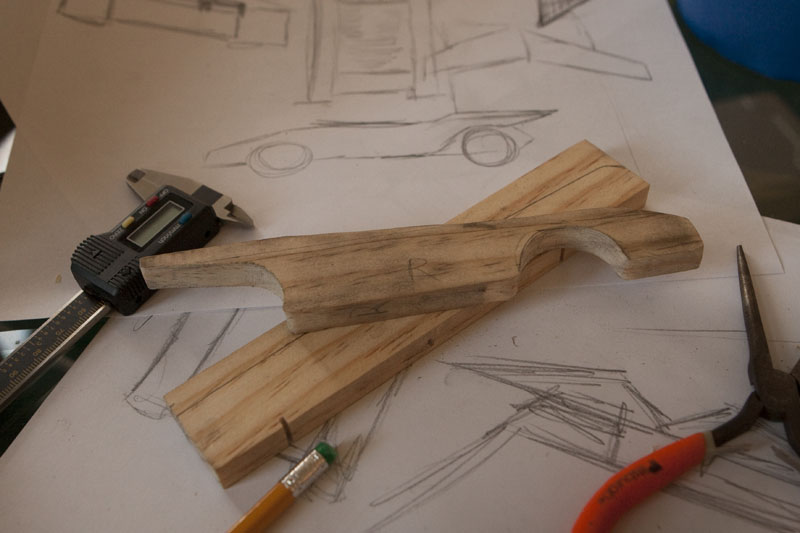
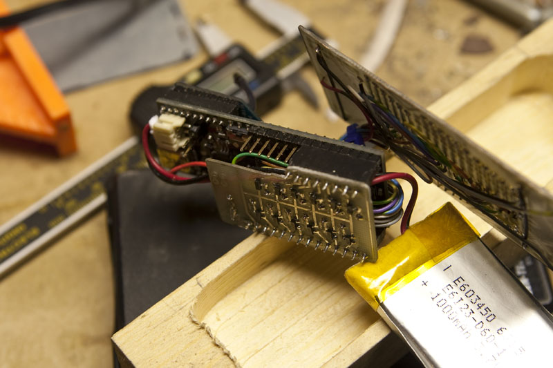
After designing the car, I needed to route out the innards where everything would fit. This was a little easier on paper than it was in wood. Eventually, it started to come together. Making a long story short, I got everything together and it worked great. This was my first real Xbee project. I really liked that I got feedback from the car which was sitting like 60 feet from me. Of course I had to program the Arduino to do so. All I needed to do to trigger an effect was just type a letter into the serial command box in the Arduino IDE. I had about 14 different things I could have it do.
Edit: (News) – My car is on Sparkfun’s Front Page!!! Call it my Andy Warhol 15 seconds. :0)
Edit: (Clarification) – No, I am not employing a “joule thief” circuit in the car. We get to name the cars, and I felt that the name fit. Some folks have asked if this is an “official scout issued” PWD kit. Yes it is, but I used 2 kits. The finished car is legal weight, but just scraping by. The wood weighs almost nothing as it is more or less, a shell. When I weighed it after finally getting all together, it was over by quite a bit. I had to hollow out just about every place that was thick enough to be drilled. I avoided the spaces right around the wheel grooves as I did not want it to bust through during the race. If you look at the front picture on the video, in the reflection in the glass you can see where I had hollowed out the sides. Drilling a car that was already completed was a pucker factor of about 12. I really thought I was going to blow out one of the sides. But even that was not enough, when it raced, it did not have the left screw in place as it pushed the car over the legal weight of 5 oz..
Eagle Boards, Schematics, and Arduino Code


This is simply gorgeous… do you mind sharing the pcb files and the code?
Sure, let me hunt it down and figure out how to post it. The code is a little goofy, but it works.
The code and boards are now up. I went through the code and commented it a little more. Hopefully it is clear
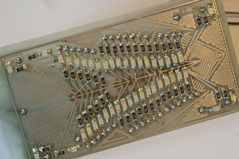
The LED board is connected to the driver board by wire. Due to the space needed inside the car, I was worried about wiring right up to the edge. I did not know how much space I would have as I was building the board weeks before the car was even out of the box. I tried to keep everything as close to the center as possible. The pads in the center (back) are there for attaching a wire to say line 1, then line 7, then line 13. All 3 are attached by 1 wire to the driver channel. Yes there are more elegant ways I could have wired it, but it was only intended to be a 1 off. Also, because of this, Eagle gets a little fussy because it would like to see everything connected. This is why you will still see air wires. On the driver board I made a cut out where the programming header is connected to the FIO so that I did not have to disconnect the board every time I wanted to upload new code. It is still a tight fit, but it works. +3v runs down the center line. There are 3 empty header pads on the driver board to make wiring a little easier. I like to have all my wires come from roughly the same place. Also I brought out the switch pins as well. I did not have time to do this, but it would have been nice to have an on/off switch say under the car so I would not have to take the car apart every time I want to turn it on or off.
How did you etch your board? I have found various etching methods online, but have been unable to get that clean an etch. I mean that board looks fantastic, good clean lines. Can you share your secret?
I use the PulsarFX printer sheets. I tried many other flavors and they always look like I scribbled them with a crayon. I had hovered over the pulsar website off and on for like a half year. Finally I gave in. My boards have never been better. I mean, you spend all this time in eagle making all the traces look nice (er… em… I’m not the only one am I) just to goof it up on magazine covers.
The other thing I found was the actual toner makes a big difference. I found out quite by accident. I was printing at home with frustrating results. I was working late one night and made a print at work. When I transfered that one it was much more solid. I went to Frys and bought a name brand (not generic) toner cartridge and got the same results at home. The Pulsar stuff took it from better to darned near perfect.
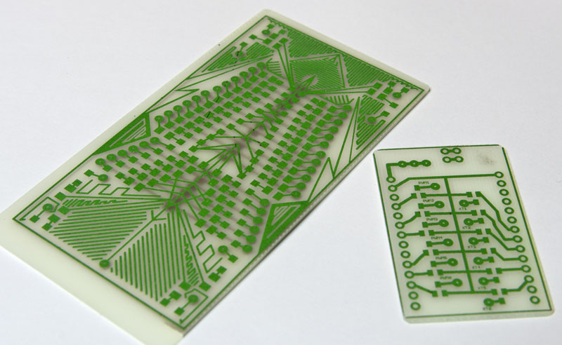
I have actually been working on a post that will kind of line out how I do them. More, It is a double sided board. I looked like mad to try to find something that clearly showed how to do a double sided board without massive headaches. I tried a number of ways, but the best way I found was actually a couple of extra steps in Photoshop. It makes life much easier. Well, you will still get a minor sinus infection, but not a migraine. :0) I have mass hours at work these days, but will finish the post up ASAP.
awesome,
ya know you could sell these ! cost for one ? im a big pinewood derby racer and pine head and my kids also.
Thanks. I suppose so, but being the tech support would be a bear. Asside from that, all the componants make the car design rough due to the weight. Skinning that thing down to weight was rough. Not saying that I wouldn’t, but I made it because I had an image in my head I had to make. I love the pursuit of the dream. Doing it repeatedly for a buck would take so much out of it. The files are there, you are welcome to download it and make one. If I can make it, I am sure you could too.
Hello –
I love the design you came up with, and it looks awesome. I know this blog entry is extremely old, but I wanted to use your designs as a jumping-off point for something that my son’s car will have. I will preface this with letting you know that he and I are just now getting into Arduino and exploring electronics together, so we are on the newb-ish side. I was hoping you could provide a little more information on the driver board schematics that you created, and maybe go into a little more detail. I tried viewing the schematics and Eagle files you uploaded, but they won’t load for me when I try to open them. Do you have any updated schematics or any detail you could provide on that?
Thanks again!
Wow, awesome. Thanks for your interest. Yes, I can try to find them again. But I will warn you, that this is not exactly a beginner project as there are several layers of complexity. I mean compared to a project a friend of mine is working on… a garden roaming robot which tests for soil conditions… perhaps it’s not that difficult. You have the car thing, so you are dealing with weight restrictions. Be careful of paint as it will add more weight than you think. Then there’s the size of the electronics, how to power them, the design of the electronics, , how to etch them, how to program them, and somewhat related, how to talk to them remotely, and lastly, how to wake it up if it gets stupid (which I never managed to do (I ran out of time)). But I learned a ton while making it, but know it was it was pretty self abusive given the amount of time (something I seemed to do every year around this time).
I know this was made long before Eagle was purchased by Autodesk. I have not tried to load it in quite some time, so I suppose it’s possible that they changed something, but I thought it was supposed to be backwards compatible. What version are you using?
Again, It’s been years since I built this, and I am away from my files to check, but to pass the general idea… the driver design… it was essentially the output pin, to the base of the transistor. It was only 3.3v, so no resistor. The leds were then sourced from 3.3V to the LEDSs through the Transistor (collector to emitter) then on to ground. This way the voltage was eaten up by the LEDs therefore putting less stress on the transistor (as opposed to powering through the transistor into the LEDs and on to ground). Obviously there was one transistor per “channel” of LED. I called them channels as I am a sound guy and it made sense. I remember the challenge being trying to make a circuit into something artistic. There are extra paths added all over the place added for artistic sake which would probably upset many engineers somewhere.
EDITED FOR CORRECT VALUES and FOLLOW UP
Update on the files. I downloaded the file, unzipped and brought it into Eagle without issue. I am not sure what is goofing up for you. Does it provide a specific error?
Great MYX, thanks very much for the reply!
As far as what we will be attempting (and we have a whole year to suss out the electronics at this point since we just finished up with the derby for this year), we will be doing a Back to the Future Delorean since it will be his last year in Cubs and we want to go out with a flash. 😀
I completely understand the self-abuse thing you mentioned, as we seem to go through that “cramming of it all in” every year with my son’s cars. The scope of our vision always seems to eclipse the time in which we have to realize it. That’s why I wanted to figure out all the hard stuff (i.e., all the electronics), earlier in the year this time to make the actual assembly of the car a little easier before the derby next January.
Basically, we will be recreating the blue Flux Bars that are on the front and back/top of the Delorean, with a few other bits thrown in like head and tail lights, etc. We were thinking of having them trigger after the slope of the track, so instead of an xBee, we’re looking at either a tilt switch or accelerometer to activate the code, which will be set to flash for a certain time. (Luckily we have the average times for everyone’s runs for the past two years, so we know the entire run itself is only about three seconds or so of action even for the fastest of cars, which allows us to extrapolate timing from there). We don’t need to worry about having the PCBs be all fancy and artistic like yours as they will be hidden within the car. So as far as the extra paths you created, that’s not an issue. This will be strictly functional. 🙂
The size and powering of the electrics I think I have worked out at this point (hooray for LiPo technology!), though I’m still trying to understand LED driver circuits and how they work. This is the area where I’m most shaky. I understand using a resistor to limit the power going through an LED so as to not burn it out, but creating a driver circuit to boost the power from a 3.7V battery to run a string of LEDs is where I’m still trying to learn. Coding-wise I’m not too worried, as I’ve had a little experience with that sort of thing before, but the design of the electronics side has me a little baffled. I have the general overview of what I want to do, but the actual layout and design still need some work. I’m leaning toward flexible PCB to get the shapes we need on the car, but it’s all still very much in the blueprint stage at this point.
At any rate, I really appreciate your response. That helps to clarify things a little with your layout. Any other tips or schematics you want to share with me would be much appreciated as well. If you want more details on what we will be doing, I can certainly provide them to you via email or in the comments section here. Maybe I’ll write up an Instructable on this when it’s all said and done. 😀
Hmm, yeah I tried to load the schematics in the Eagle I downloaded, and they wouldn’t pull up. I don’t remember the specific error they gave, but I’ll have to try them again when I get home. I will say that I don’t have a full version, just the trial version they offer, so maybe that has something to do with it? If not, I’ll have to see if I can find a good viewer for those file types somewhere. I’ll try some more and let you know if I continue to have issues with them.
Hey ElChick,
Right, so a year gives you plenty of time. That’s a great advantage. I say, go all out then.
As to talking about it, I was initially going to say let’s take this off here and do this conversation via email. But then I realized that the reason I have been able to do what I am able to do was a resuilt of conversations on other people’s blogs where the questions pull out the valuable bits. So many times we get comfortable with what we built, because we built it, and other’s don’t have the advantage of the experience of walking through it. We can try to describe it however we want, but we WILL miss important points, so, I would like to, as much as possible, leave the conversation here, for the benefit of someone else later. Cool?
Okay, my thought process in the design and why I got to the place it got to. Early in my thinking (which yes, began not too long after the pervious derby) I started putting together what I wanted it to do. My original plan was to use an accelerometer (mentioned above). I figured that I could chart the drop and use that spike as a signature to trigger the sequence*. There were several factors which kept me from doing this. The major one was kids. In our pack, we allowed the kids to ‘run’ the cars in specially built car boxes which put the cars in lane order. One group of kids would be at the table where all the cars were and when a race was done they would take the cars to the track. At the same time, there was a set of kids which would be delivering the cars, and would return after the race, so we always had cars on deck, so to speak. Having the kids as a part of the thing was important, but this also presents a risk. More than one time I saw the kids drop the box. More than once I saw them turn and play and move the box in ways that would bounce the cars around a bit. Never like crazy shaking, but if they would turn around, that could get the cars to move in the box. If the car hit the front of the box that could be considered a spike at which point the lights would start flashing. I didn’t want the car to start blinking like crazy until the race happened, so I needed a way to prevent the random spikes from happening. I thought about adding foam to the front and back to lessen the shock. I thought about… well too many things really. Another thing I was concerned about was the possibility that the kids would get wise to the car being movement active and then have it become a play thing. If I were a kid and bounced a car and it went apeshit, I would do it again, right? I wanted the there to be surprise when it raced for the first time, so I needed to do something where I had control the whole time. Hence the wireless control via computer. As to my board designs, I did some stuff that made Eagle most unhappy. I was pretty new at it, and there were going to be 2 boards, so I didn’t know how to tell Eagle that some connections would just have to be ‘trusted’ as okay. I knew where the inputs and ground to the LED board was coming from, but it didn’t and it was constantly telling me about it. This is a really good reason NOT to use autotrace on a project like this.
Another worry for me was how long the battery would last. LiPos do not like to be discharged passed a certain point. While I had to do a lot of homework to figure out how many LEDs I could power at once, there was no way I could think of to figure out how long the battery would last as the flashing was never consistent nor fully on. There was also the cost of the wireless transmission (xBee). I had already planned keep that to a minimum, but I still took a hit there too. There was then the problem where we had to submit our cars on the Friday before the race (Saturday night). Once the car was submitted, it was hands off (no chance for last minute weight additions n such). I was fretting about how long the battery would last if it was submitted already turned on. Being a den leader, I asked at our pack leaders meeting about permission to touch the car long enough to turn on the car once the event was about to start. Their response was awesome. More eyebrow twists than should be possible (and another reason why you should do this… peoples reactions… much fun). “Turn the car on?” they asked. I had the boards finished at that point so I pulled out my tupperware and turned it on. Needless to say, this sidetracked the meeting for about 10-15 minutes while I answered everyone’s questions. They gave me a resounding YES as to turning on the car. So, bottom line here, get permission to power it up at the event so there’s no worry about battery life.
As to your plans… my driver board was designed to fit directly to the FIO board. If you are not using a FIO, then there’s no need to use my design as a jumping off point. You can start from scratch which as I have learned, might be a better idea than starting from pre made. When I made my camera triggering system a few years back (a post which is yet to be written) I tried to base it on the Adafruit Boarduino. It was a great thing at first as I got to get into the design and start moving things around. But eventually I found that there was so much extra work to be done because her ideas for a streamlined board didn’t align with my ideas about what I was trying to accomplish. So most of it was eventually scrapped and I started with a clean schematic. But if you can get the files to work (grrrr!) you are welcome to start from there. I am using the free version of Eagle. It’s version 7.2 and I am working on Mac now, I was on PC then. I don’t understand why it wont work for you. :0(
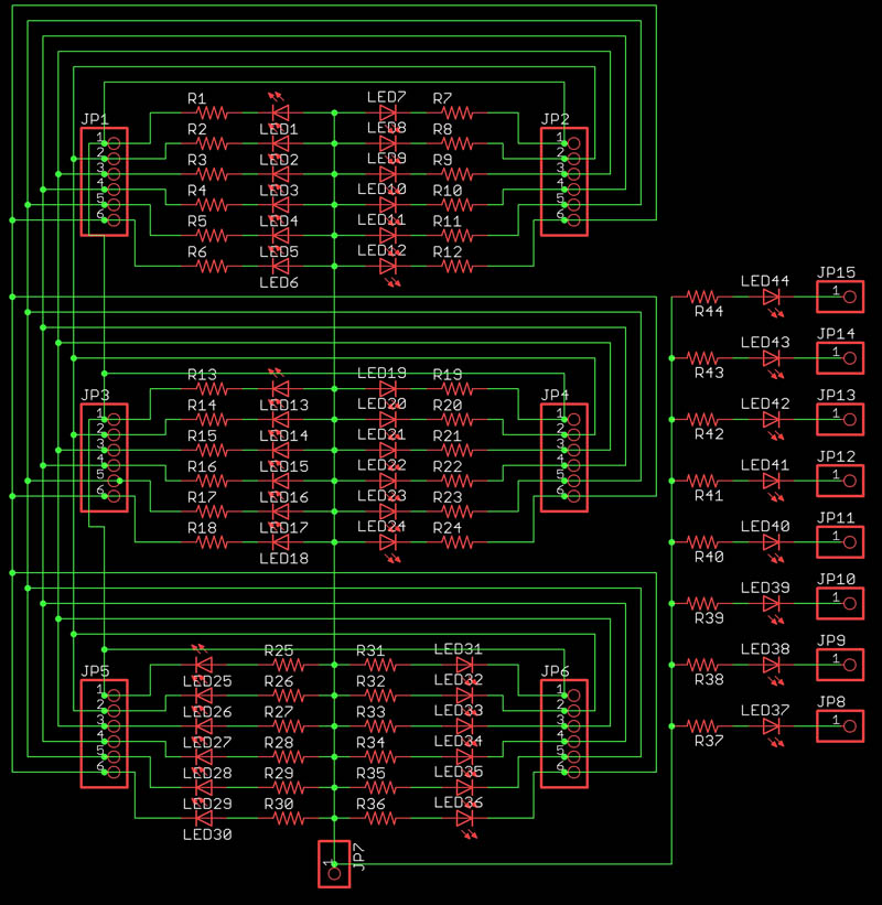
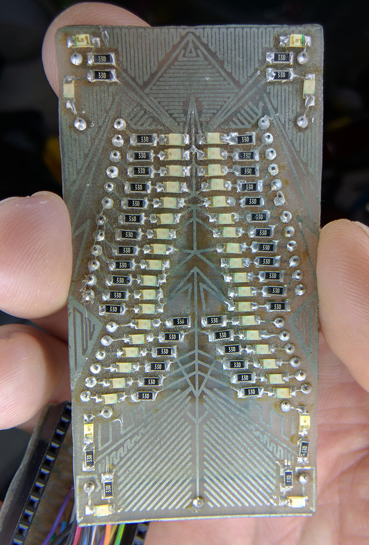
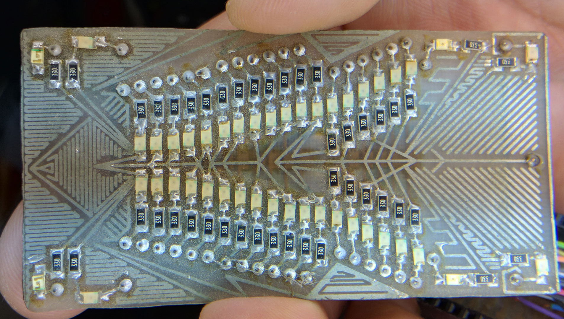
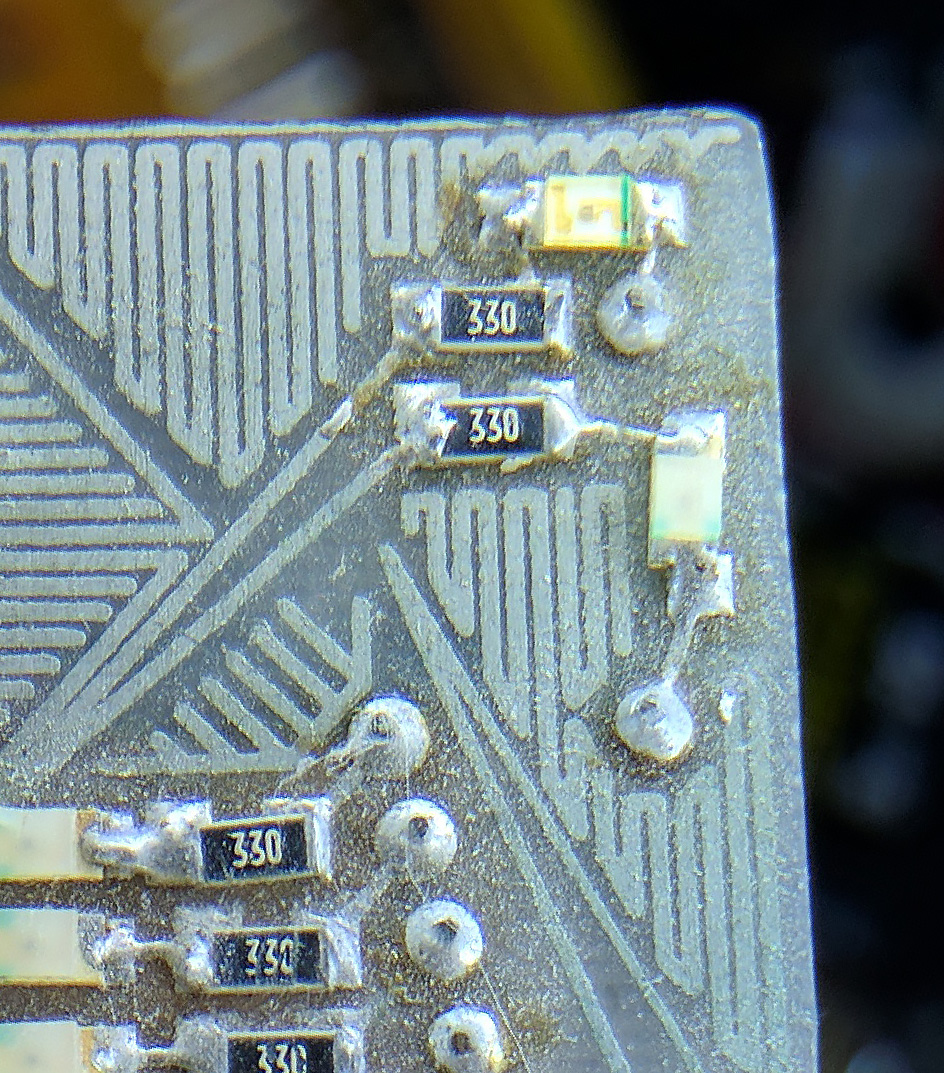
Will this be your first experience in making your own board? This was a daughter board to the FIO, so you can think of it like a shield for the true Arduino. When you mentioned not understanding how to run a string of LEDs. There was no true string at any given time. If you look at the ribs of the red LEDs there is a center line that runs down… well… the center. (sorry). That is 3.3v. So say on channel 1 what you have is 2 red leds being powered from 3.3v. Each red LED eats roughly 1.5v so that’s 3v and then a 330ohm resistor to keep things happy. Channel 1 is repeated 3 times up the back of the board. You will notice a solder point next to each rib. That goes to a trace on the back of the board. The 3 traces for channel 1 were then connected via physical wire. There were 6 channels of PWM, each channel had 6 LEDs on it, again being sourced and used prior to the transistor, and the transistor connected to ground. The grounding is what pulled the voltage through the circuit.
The blue and green LEDs were very similar except they were each powered directly from the 3.3v as they cost 3v each, and again a current limiting resistor per LED. These were each then sent to their own transistor as I wanted individual control over them.
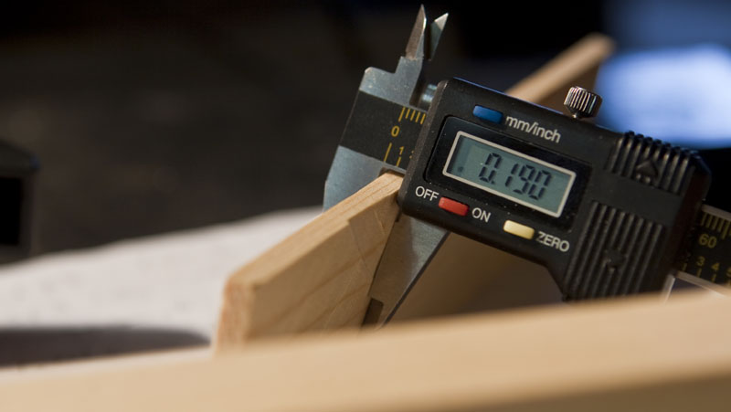
As to wiring through the car to external circuit boards, the problem is drilling accurately. It’s fully doable, but drill holes are never pretty. Grab some little micro drills from Harbor freight. See if you can find someone who works in the telephone industry. They use this little tiny solid strand wire which is perfect for this type of miniature wiring. It makes getting wire through wooden holes much more palatable. If you are putting LEDs under the car (awesome on aluminum tracks) be careful to avoid areas which might come in contact with the center rail (the thing which holds the cars to the tracks) If you can get access to it, go and measure it with a caliper to get your clearances. You want that car to fly. :0)
*Sequences… If you haven’t yet, get familiar with both arrays and “For” loops for turning on and off your leds in specific sequences. You can build number patterns in an array, and have those numbers represent a pin.
This is the project where I embraced both and it was such a massive time savings over the way you originally learn…
digitalWrite(ledPin, HIGH); // set the LED on
delay(1000); // wait for a second
and so on.
Wow!!! Massive response!! I’ll have to take a little time to go through it before I respond more in detail, but I’m perfectly happy to leave the commentary here on the blog. I agree with what you said about learning from these types of conversations. A lot of what I know has been gleaned from forum conversations like these.
An update on the Eagle issue……an uninstall/reinstall fixed the problem. I’m now able to see your designs!
I’ll see if I can respond more in detail about what we are planning a little bit later on. I’ve written out a sequence of events outline, but I’ll have to dig it up before I can post it. But I at least wanted to give you a quick update, and say thanks again for helping out!
Okay, so here is the outline of what I want to happen with the run. I’m still pouring through your last comments and don’t have a full commentary on those yet, but here at least is the sequence of events that I would like to see with our car.
~ Car is placed onto the track. ~
Point A – At The Starting Gate.
1.) The boy places the car onto the track, and then presses the “on” button once it is sitting at the gate.
a.) The headlights/tail lights turn on signalling code readiness, and the accelerometer/tilt switch
is reset and ready for input change. (Already on the slope, so shouldn’t trigger until slope changes.)
b.) ~OPTIONAL~ Engine sound turning on/revving.
~ Car is released from the gate and begins run. Nothing but headlights/tail lights are on going down the slope. ~
Point B – At The Bottom Of The Curve Of The Track.
1.) The tilt/accelerometer switch registers the change in declination angle and activates the Flux bar lights.
a.) Blue lights on the Flux bars activated at a steady 50% brightness and remain so till Point “C.”
b.) ~OPTIONAL~ Flux Capacitor charged sounds turn on.
Point C – About .5 Seconds Or So Past The Curve And Into The Straight.
1.) Timing in the code triggers the Flux Light Sequence changes.
a.) Blue lights on the Flux bars quickly ramp up to 100% brightness and remain steady throughout.
b.) White lights embedded within the Flux bars begin to randomly (timing) flash at random (PWM output)
brightness levels (50% – 100%?)
c.) Wormhole Emitter light steady on at 50% brightness and begins to randomly (timing) flash at random (PWM output) brightness levels (50% – 100%).
d.) Fire Trail lights embedded in the wheel wells activate & begin to randomly (timing) flash at random (PWM output) brightness levels (50% – 100%).
e.) ~OPTIONAL~ Wormhole sound sequence plays.
Point D – About 1.5 – 2 Seconds Past Point “C” Into The Straight. (Exact time based on timing found in test runs beforehand.)
1.) Timing in the code triggers the Flux Light Sequence end.
a.) Blue lights on the Flux bars on at 100% brightness for about 100ms? and then turn off.
b.) White lights embedded within the Flux bars quickly ramp up to 100% brightness for about 100ms? and then turn off.
c.) Wormhole Emitter light quickly ramps up to 100% brightness for about 100ms? and then turns off.
d.) Fire Trail lights quickly ramp up to 100% brightness AND REMAIN ON for about 250ms? or Point “E.”
e.) ~OPTIONAL~ Time Jump sounds play.
~ All Flux Sequence lights off just before the car passes the finish gate. ~
Point E – Track End Point Past The Timing Gate.
1.) All programs turn off and reset for the next run. Code ends.
a.) Fire Trail lights turn off.
b.) Headlights/tail lights remain on for about 250ms? past the fire trail lights turning off, and then turn off
themselves.
c.) All lights off signals code end and reset for next run.
Well, you can at least see what the outline plans are for the sequence that I’d like to accomplish. The optional sounds would be audio grabs from the movie played through a small speaker in the car (I play around with N Scale trains in another hobby, and such tiny speakers are available for locomotives in that size). Due to the derby car weight restrictions, that probably won’t happen though. My focus is on the lighting at any rate, and if we have extra time to try to work out the sounds I’ll look into it.
At any rate, I’m thinking of having all the blue flux lights be on one “channel,” each of the embedded white lights in the flux bars be on their own channels to allow for random blinking at different brightness levels***, the wormhole emitter on top of the car be another channel, and the fire trail lights be their own channel. (Can’t have actual fire trails on the track sadly :P, but I figure that fire colored LEDs will look nice reflecting off the aluminum track surface). That way with the separate groupings of LEDs, I can control all the sequencing and brightness levels in the coding. I’ve seen things on multiplexing and LED matrices, but it’s all a bit confusing to me. What I want to do is a bold plan, I know. But hopefully with the amount of time we have to play around with it, we can get it all sorted out, and I can learn and be taught enough to make it happen.
I will say that our pack seems to be slightly more lax about the car rules. The weight restrictions and everything are in place, but the cars just sit out on a table, and each boy handles only their car……in a perfect world, at any rate. I’ve seen some of the older kids at the end of the track pick up the cars after the race is done whether or not it is theirs….and I can see a cool, flashy, blinky car being a great temptation to pick up and handle after the race too. At any rate, the cars are brought the day of the race, and after the weigh-in are placed on the table to await the races. So some of the issues you had mentioned won’t be a problem for me.
In thinking over what I wanted to happen for the sequence of events, I was also trying to work out some of the issues that you had mentioned led you to the wireless transmission for your solution. I was thinking that having a button to press once the car is ON the track to activate the code and make the mercury switch or accelerometer in the ready to transmit would solve the issues of it randomly activating, thus helping to preserve the shock and awe of the first run. It may also help to preserve the battery life, as it would only be active once the button is pressed.
Anyway, those are my thoughts for right now, and should give you a jumping-off point to at least have a picture of my vision of my son’s last derby car as a Cub. Please feel free to check things over and suggest any changes you would make. I’m not overly experienced with the custom-built electronics/Arduino side of things yet, so any help and insight you can provide from your experience would be great.
*** If you watch the movie sequences, there is a lot of flashing happening in the air AROUND the car as it jumps. I can’t recreate anything like that in the air, but thought that having some white lights in the blue bars flash and blink would help to simulate those flashes. I plan on putting thin, custom-made styrene covers over the LED PCBs to hide the boards, but to also diffuse and smooth out the light and make it blend into one homogeneous light source. I figure randomly powered and timed flashes of white among that blue would help to simulate the look.
On a separate note, is there any possible way you could email or upload a picture of the back of your LED board (the picture above of the front of the LED board with all the components soldered on already is most helpful), and the front and back of the driver board? I can kind of understand the way the traces flow in Eagle, but having an image of the physical boards and wires helps my mind to wrap around how things flow, and what connects with what in the physical world. Sorry, but as I stated before, I’m rather a newb at this and know just enough to be dangerous. 😀
Seeing completed work like yours and dissecting it helps immensely in my learning process, even if I’m not following the same pattern. Again, I want to thank you for helping out where you have already. It’s most appreciated.
This one might take a little time as I will have to take the car apart to get to the backside. I will do it asap.
Thanks very much, I appreciate it. I’m not in a huge rush, so don’t feel pressured to do it immediately. I was also checking out the Corona Wire car. Those UV lights along with the EL wire and black glossy paint job are killer!
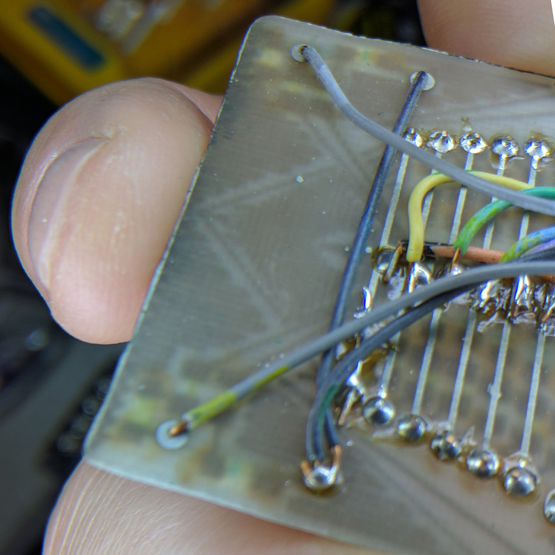
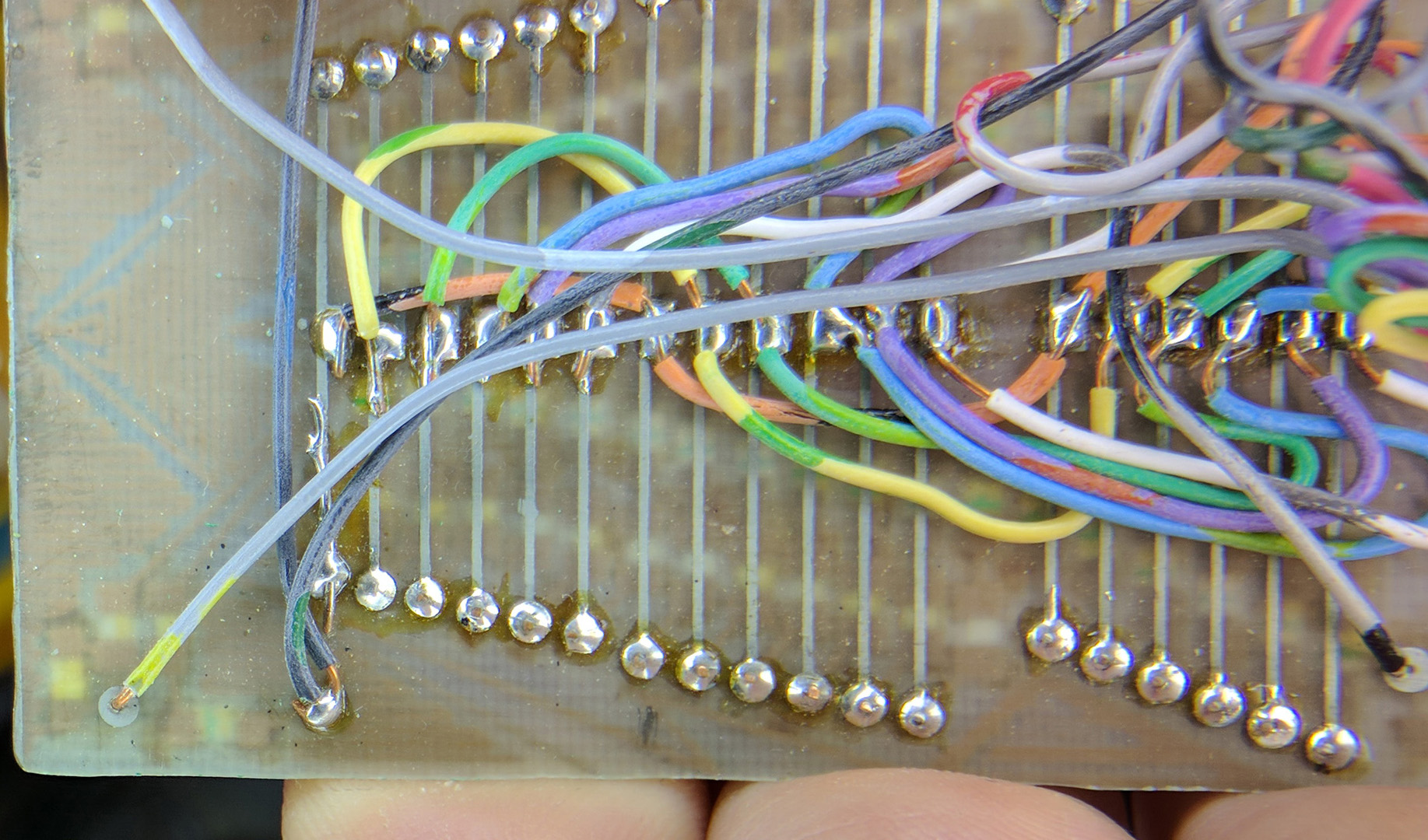
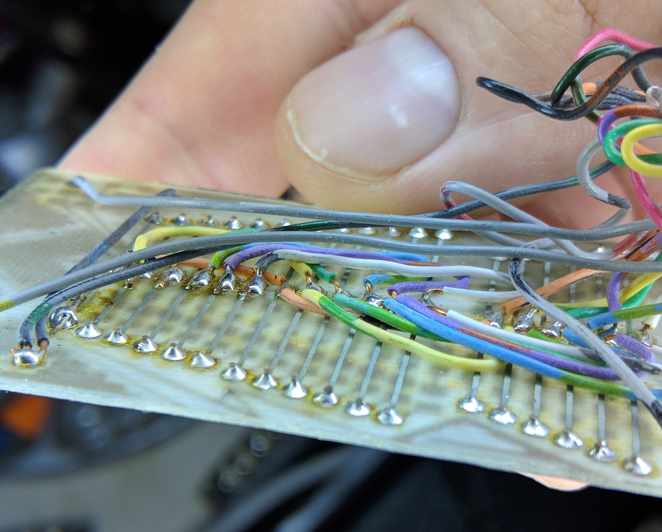
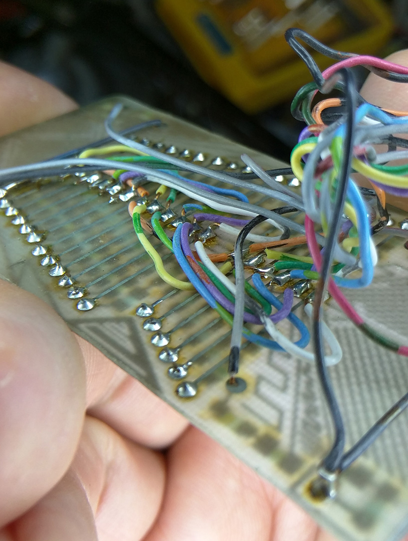
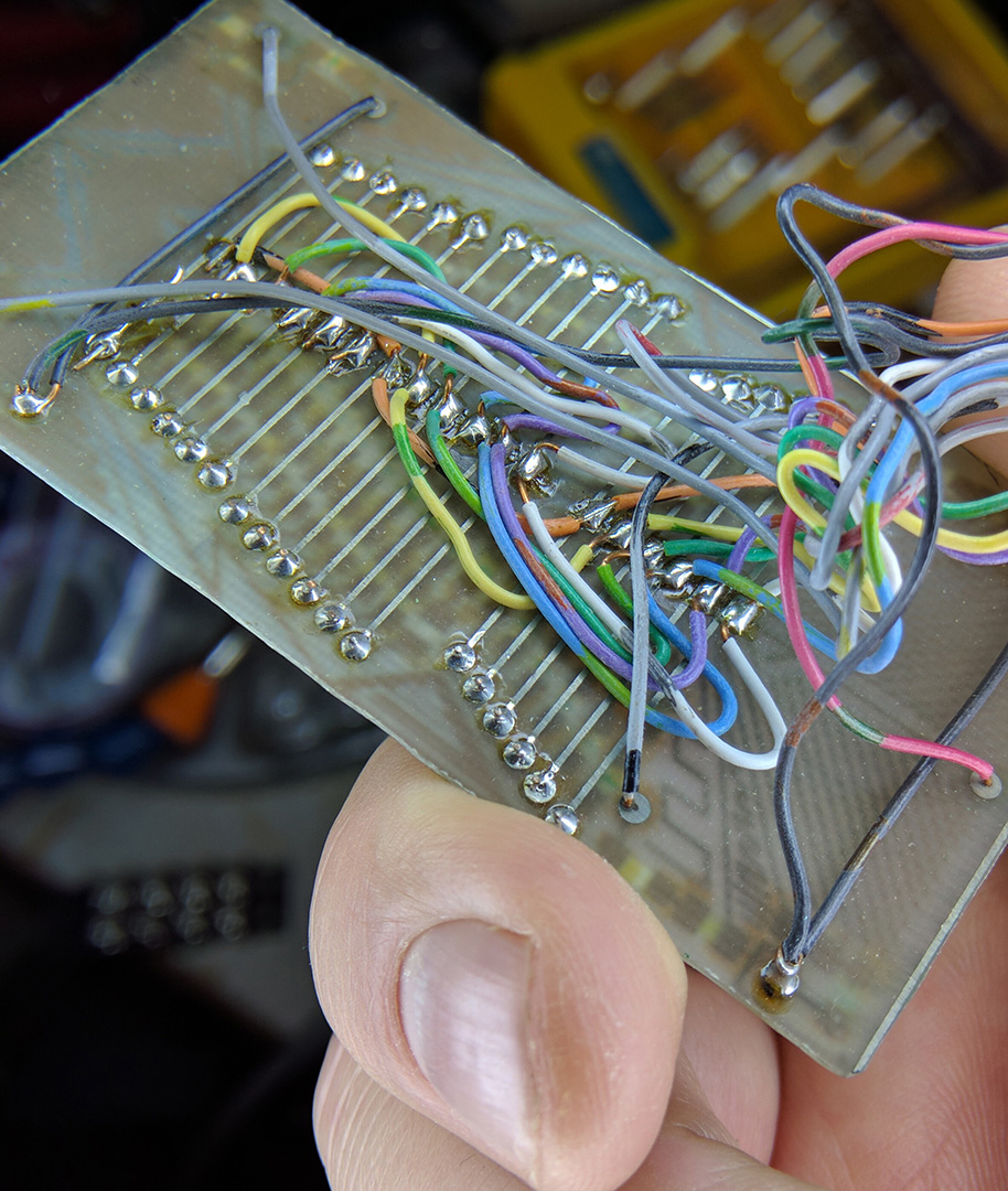
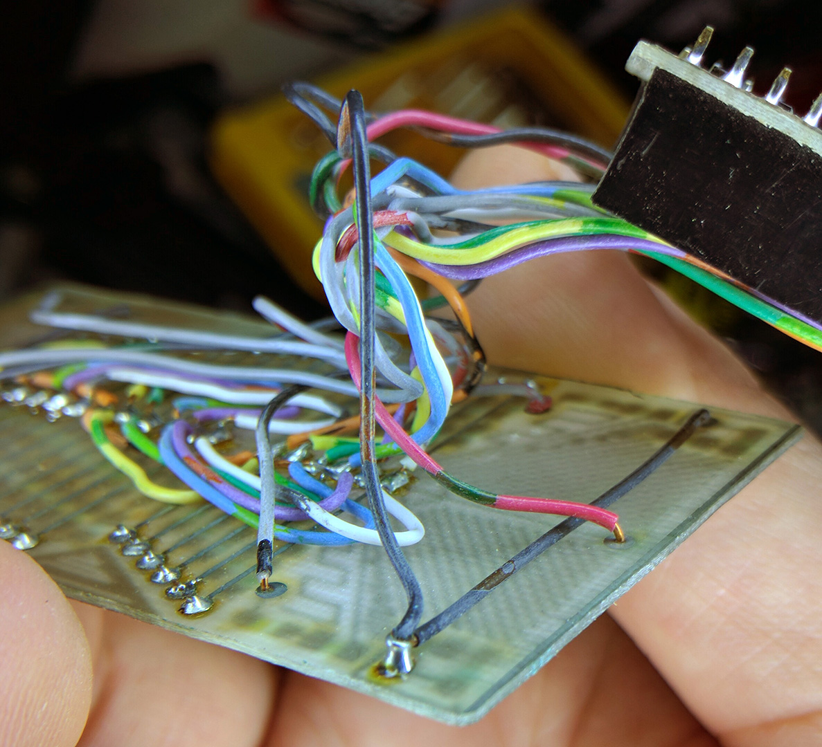
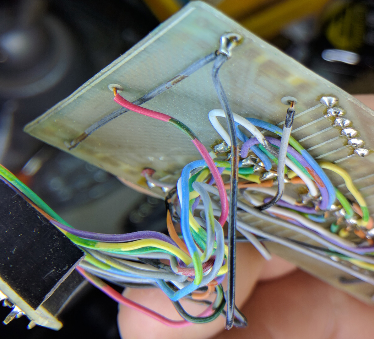
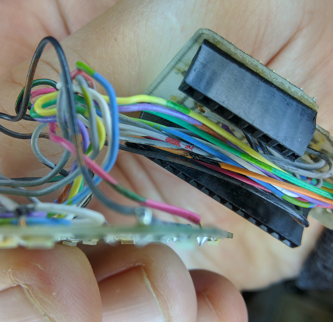
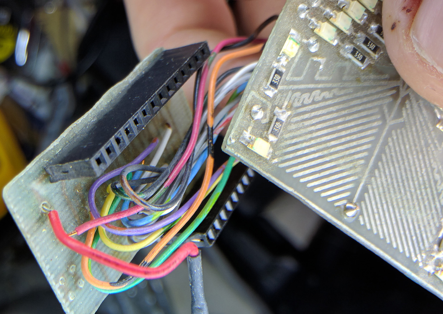
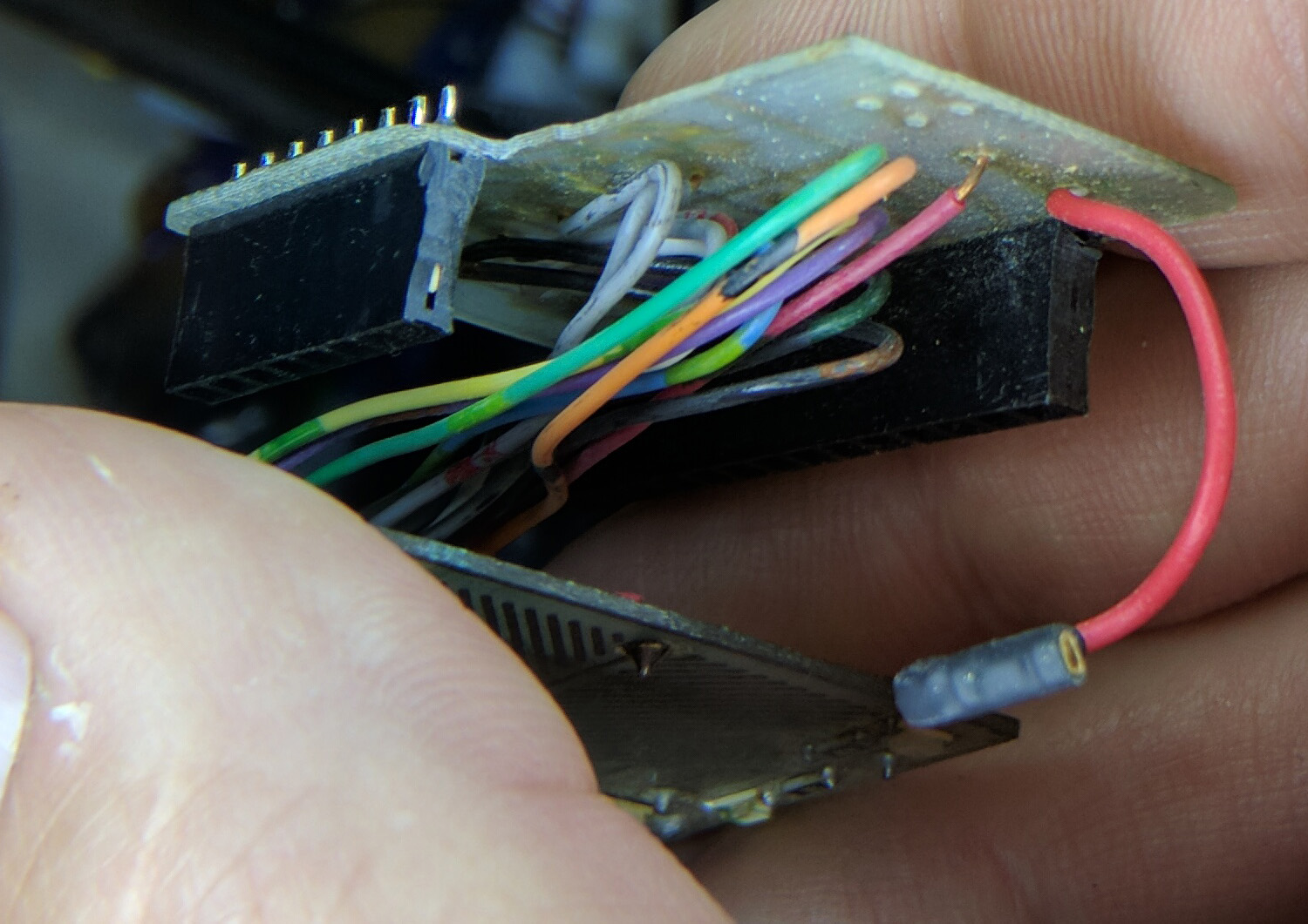
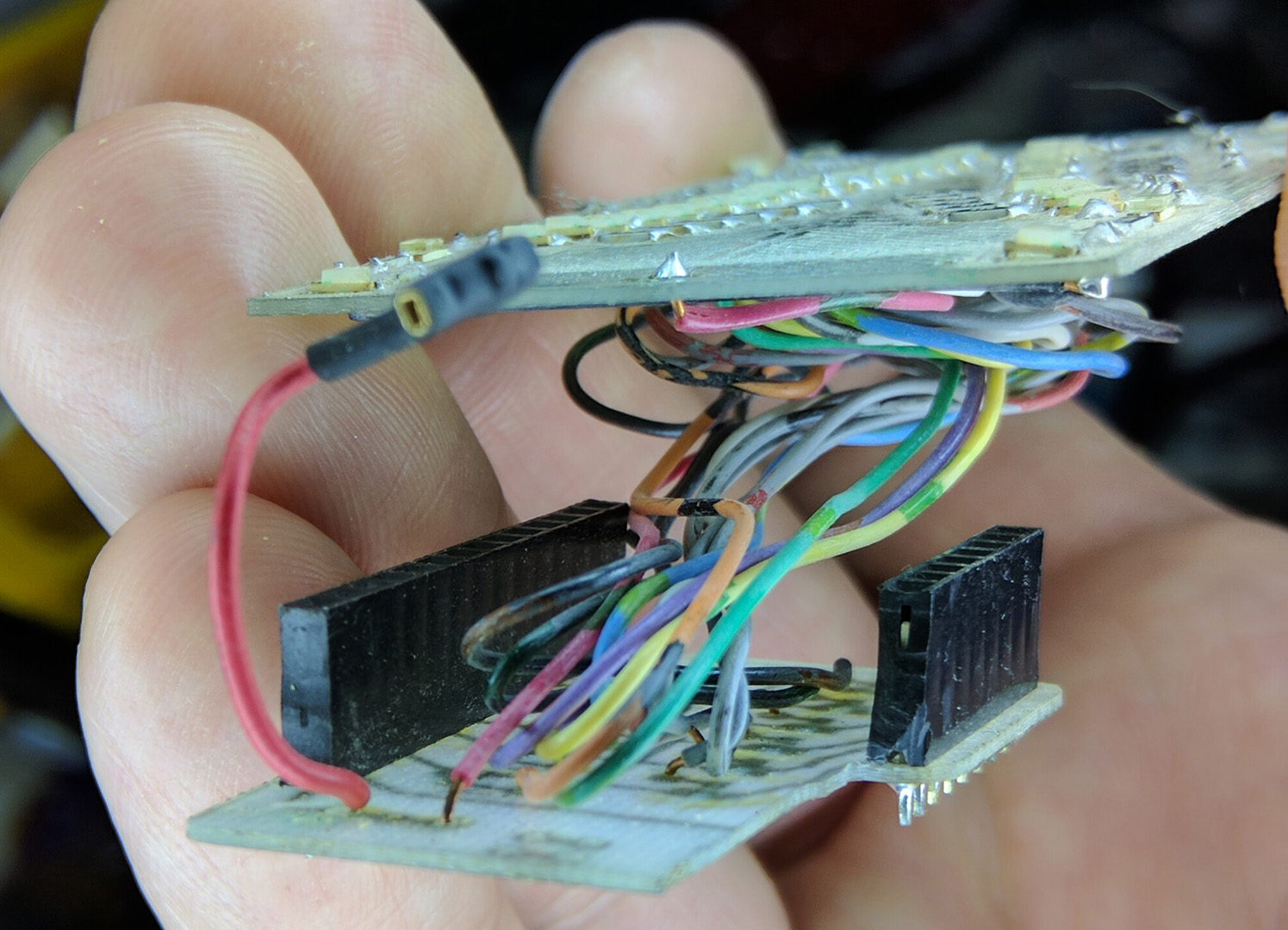
Hey ElChick, I have uploaded some images showing the not so sessy side of the electronics. Once you start to pull it apart to get some photos, it looks even worse, so… you have been warned. heh heh.
So what I tried to get you was the important bits from many angles. This is based on what I am looking for when I start diving into peoples pictures. Where does that wire go, if they would have just taken a photo a little more to the left… So, yes, there’s a brazillion photos there, hopefully it answers any lingering questions. As to the LED board, you can see that I was S curving a single wire through each layer of it’s channel. It was getting so tight for space in there. I needed a little extra wire so I could separate the boards look at stuff while troubleshooting. So, I formed the wires so they would fold in on themselves. When I just pulled them apart, it was like everything just went SPROING! It was all tightly packed and when it was pulled, it just let loose. You will see how the colored (phone system) wire made tracing the various lines much easier. You will see a loose red wire with a hole at the end. This was so I could connect to the incoming battery power on the arduino pin. Ground was handled connected within the IO sandwiched connections. I cut a Schmartboard female jupmer in half for this. I think it was a worthy sacrifice.
I hope this helps.
Cheers!